
Container with diverter bar

a diverter bar and container technology, applied in the field of containers, can solve the problems of insufficient tension between the notches of bags, waste can lack a retainer attached to the lid, etc., and achieve the effect of convenient transportation and ease of shipmen

Active Publication Date: 2019-10-31
HMS MFG
View PDF0 Cites 7 Cited by
  • Summary
  • Abstract
  • Description
  • Claims
  • Application Information

AI Technical Summary

Benefits of technology

The invention is a container with a diverter bar on the lid that can be easily shipped and stored. This design also keeps the diverter bar in the correct position on the lid. The containers can be stacked on top of each other, making it easy to transport and display large quantities of containers. Overall, the invention improves the efficiency of shipment and storage of containers.

Problems solved by technology

However, the frictional engagement of the bag between the notches is generally inadequate to maintain tension as the bags receive contents.
However, the waste can lacks a retainer attaching to the lid for securing the diverter bar in a storage position.

Method used


Image

  • Container with diverter bar
  • Container with diverter bar
  • Container with diverter bar

Examples


Embodiment Construction

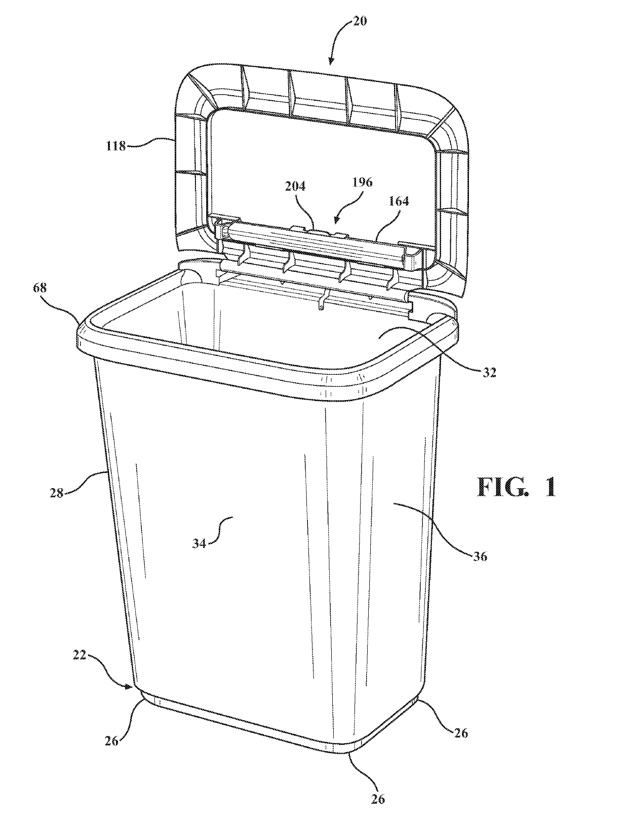
[0020]Referring to the Figures, wherein like numerals indicate corresponding parts throughout the several views, a container 20, described in accordance with one embodiment of the present invention, is generally shown in FIG. 1. The container 20 can be used to hold a pair of bags or one large bag.

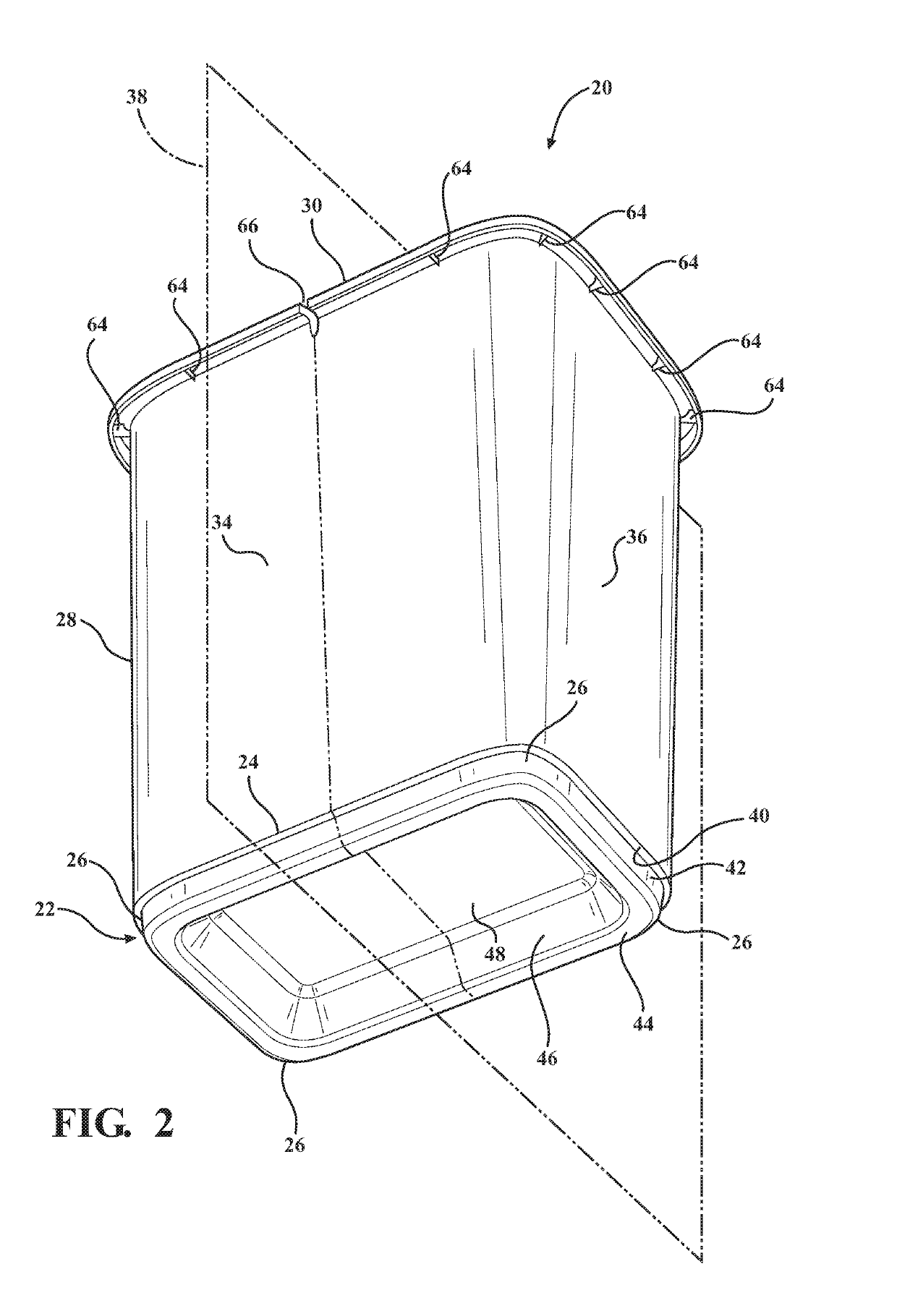
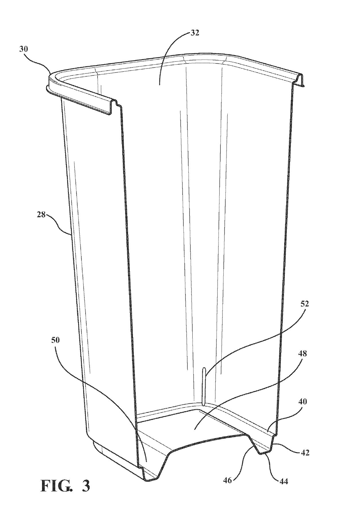
[0021]As best illustrated in FIGS. 1-4, the container 20 includes base 22 having a generally rectangular shape and defining a periphery 24 extending about the base 22 and presenting a plurality of four corners 26. The container 20 further includes a wall 28 extending outwardly from the periphery 24 of the base 22. The wall 28 defines a rim 30 spaced from the base 22. The base 22 and the wall 28 collectively define a compartment 32 extending therebetween.

[0022]The wall 28 includes a pair of center walls 34 and a pair of sidewalls 36. The center walls 34 are spaced from and opposed to one another, and the sidewalls 36 are also spaced from and opposed to one another. The center walls 34 and th...


PUM


Abstract

A container includes a base and a wall disposed about and attached to the base. The wall defines a rim spaced from the base, as well as a compartment extending between the base and the wall. A lid having an inner surface and an outer surface is coupled to the wall for covering the compartment. The container has a diverter bar for separating the compartment into at least two sections in a first position. The diverter bar has a body that extends between body ends, with the body releasably engaging the wall in the first position. A retainer attaches to the lid for receiving the diverter bar and securing the diverter bar to the lid to define a storage position. A lip extends outwardly from the body whereby the lip engages the retainer in response to the diverter bar being in the storage position.

Description

CROSS-REFERENCE TO RELATED APPLICATION[0001]The present invention claims benefit of U.S. Provisional Patent Application Ser. No. 62 / 662,263, filed on Apr. 25, 2018, the entire disclosure of which is considered as part of this application and is hereby incorporated by reference.BACKGROUND OF THE INVENTION1. Field of the Invention[0002]The present invention relates generally to a container.2. Description of the Prior Art[0003]Waste cans are well known. Generally, a waste can comprises an open-top can including a cover attached thereto, wherein the can is adapted to receive an open bag therein for receiving contents. The upper portion of the bag held within the can is often draped over the upper edge of the can, and the bag maintains its position within the can primarily by friction between the bag and the rim of the can. The bag may also be secured to the container by a ring that assembles to the rim and secures the bag with a clamping force. In order to secure a pair of bags to the r...

Claims


Application Information

Patent Timeline
Patent Type & Authority Applications(United States)
IPC IPC(8): B65F1/16B65F1/06
CPCB65F1/06B65F2210/148B65F1/1615B65F2220/12B65F1/067B65F1/16
Inventor SOFY, JANET M.BROWN, MICHAEL E.LAJEWSKI, TODD M.
Owner HMS MFG
Learn More