Connecting structure of a conductive layer

Active Publication Date: 2019-11-14
SAMSUNG DISPLAY CO LTD
View PDF3 Cites 0 Cited by
  • Summary
  • Abstract
  • Description
  • Claims
  • Application Information

AI Technical Summary

Benefits of technology

[0006]According to an exemplary embodiment of the inventive concept, a connecting structure of a conductive layer includes a first conductive layer, a first insulating layer disposed on the first conductive layer and including a first opening overlapping the first conductive layer, a connecting conductor disposed on the first insulating layer and connected to the first conductive layer through the first opening, an insulator island disposed on the connecting conductor disposed in the first opening, a second i

Problems solved by technology

However, in an etching process, it is not easy to connect th

Method used


Image

  • Connecting structure of a conductive layer
  • Connecting structure of a conductive layer
  • Connecting structure of a conductive layer

Examples


Example

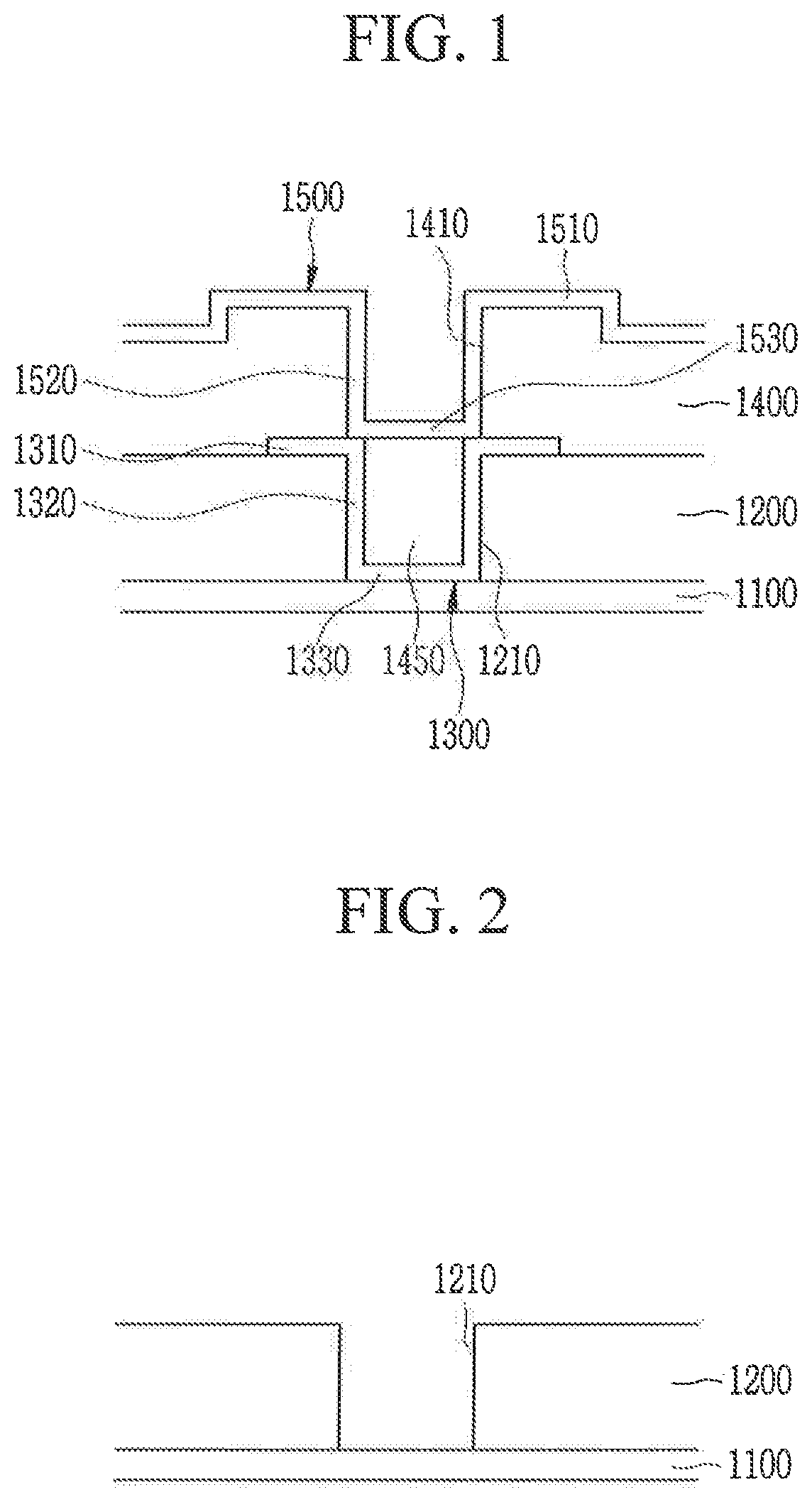
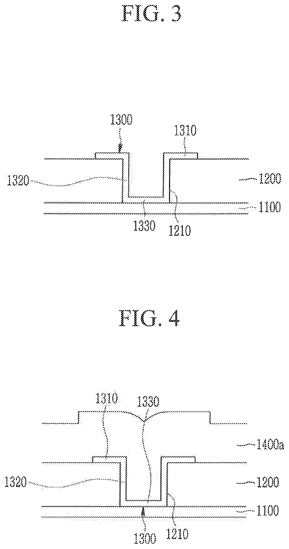
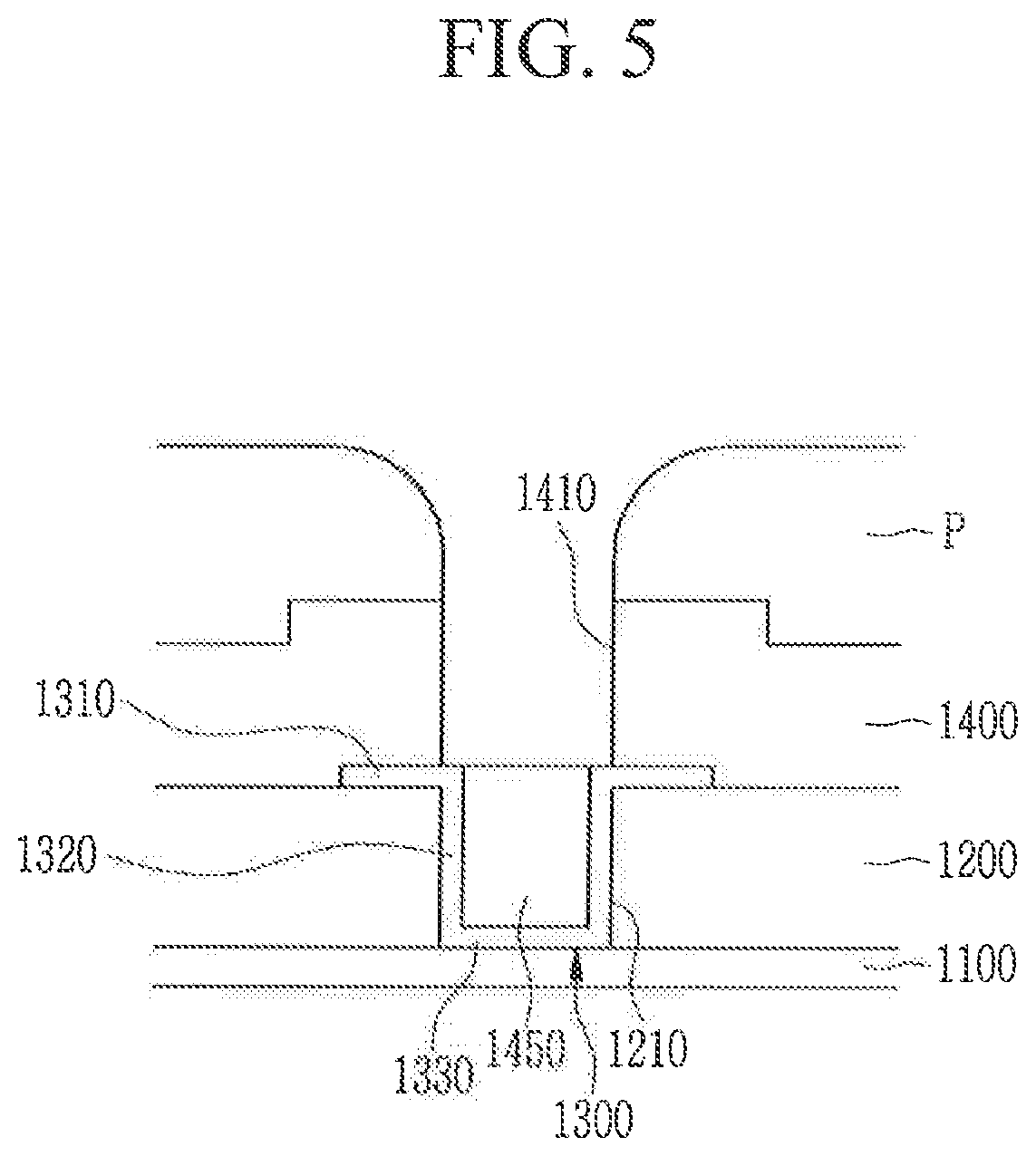
[0020]Exemplary embodiments of the inventive concept provide a connecting structure for easily connecting two conductive layers disposed with a thick insulating layer therebetween.

[0021]Exemplary embodiments of the inventive concept will be described more fully hereinafter with reference to the accompanying drawings. Like reference numerals may refer to like elements throughout this application.

[0022]Further, in the drawings, the size and thickness of each element are arbitrarily illustrated for ease of description, and the inventive concept is not necessarily limited to those illustrated in the drawings. In the drawings, the thickness of layers, films, panels, regions, etc. are exaggerated for clarity.

[0023]It will be understood that when an element such as a layer, film, region, or substrate is referred to as being “on” another element, it can be directly on the other element or intervening elements may also be present. In contrast, when an element is referred to as being “directl...


PUM


Abstract

A connecting structure of a conductive layer includes a first conductive layer, a first insulating layer disposed on the first conductive layer and including a first opening overlapping the first conductive layer, a connecting conductor disposed on the first insulating layer and connected to the first conductive layer through the first opening, an insulator island disposed on the connecting conductor, a second insulating layer disposed on the first insulating layer and including a second opening overlapping the connecting conductor and the insulator island, and a second conductive layer disposed on the second insulating layer and connected to a connecting electrode through the second opening. A sum of a thickness of the first insulating layer and a thickness of the second insulating layer is greater than or equal to 1 μm, and each of the thicknesses of the first and second insulating layers is less than 1 μm.

Description

CROSS-REFERENCE TO RELATED APPLICATION[0001]This application claims priority under 35 U.S.C. § 119 to Korean Patent Application No. 10-2018-0040628, filed in the Korean Intellectual Property Office on Apr. 6, 2018, the disclosure of which is incorporated by reference herein in its entirety.TECHNICAL FIELD[0002]Exemplary embodiments of the inventive concept relate to a connecting structure of a conductive layer.DISCUSSION OF RELATED ART[0003]A display device includes two electrodes and an emission member interposed therebetween, where electrons injected from one electrode and holes injected from another electrode are combined in an organic emission layer to generate excitons, and the generated excitons release energy to emit light. By using such light emission, the display device displays a predetermined image.[0004]As a resolution of such a display device increases, the number of wires for driving the display device increases, and the wires are disposed with an insulating layer ther...

Claims


Application Information

Patent Timeline
IPC IPC(8): H01L21/311H01L21/027H01L29/41H01L21/763H01L21/768
CPCH01L29/41H01L21/31144H01L21/76816H01L21/763H01L21/0271H01L23/5226H01L27/124H10K59/131H10K50/805
Inventor BAE, SU BINJEONG, YU-GWANGCHOI, SHIN ILKIM, SANG GABLEE, JOON GEOL
Owner SAMSUNG DISPLAY CO LTD
Why Eureka
Try Eureka