Spin-current magnetization reversal element, magnetoresistance effect element, and magnetic memory

a spin-current magnetization and reversal element technology, applied in the direction of magnetic bodies, instruments, substrate/intermediate layers, etc., can solve the problems of high power consumption, insufficient reversal current density reported in the present sot method, and difficulty in achieving lattice matching with ferromagnetic metal layer joined to spin-orbit torque wiring, etc., to achieve the effect of reducing power consumption

Active Publication Date: 2019-11-14
TDK CORPARATION
View PDF0 Cites 5 Cited by
  • Summary
  • Abstract
  • Description
  • Claims
  • Application Information

AI Technical Summary

Benefits of technology

[0024](10) A magnetoresistance effect element according to one aspect of the present disclosure includes the spin current magnetization rotational element according to any one of claims 1 to 9, a second ferromagnetic metal layer configured for a magnetization direction to be fixed, and a nonmagnetic material layer sandwiched between the first ferromagnetic metal layer and the second ferromagnetic

Problems solved by technology

However, the reversal current density reported in the present SOT method is insufficient for realizing high integration and low energy consumption.
Since such heavy metal materials have a high electrical resistivity, high power consumption is also a problem when such

Method used


Image

  • Spin-current magnetization reversal element, magnetoresistance effect element, and magnetic memory
  • Spin-current magnetization reversal element, magnetoresistance effect element, and magnetic memory
  • Spin-current magnetization reversal element, magnetoresistance effect element, and magnetic memory

Examples


Embodiment Construction

[0033]Hereinafter, the present disclosure will be described in detail with reference to the drawings as appropriate. In the drawings used in the following description, there are cases in which characteristic portions are appropriately enlarged for convenience of illustration so that characteristics of the present disclosure can be easily understood, and dimensional proportions of respective constituent elements may be different from actual ones. Materials, dimensions, and the like illustrated in the following description are merely examples, and the present disclosure is not limited thereto and can be implemented with appropriate modifications within a range in which the effects of the present disclosure are achieved. In the elements of the present disclosure, other layers may be provided within a range of achieving effects of the present disclosure.

(Spin Current Magnetization Rotational Element)

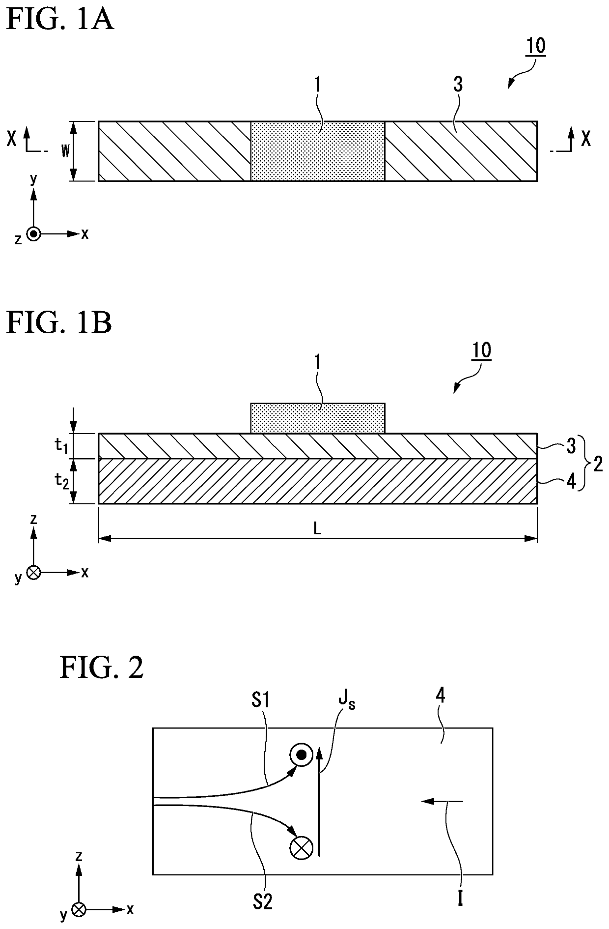
[0034]FIGS. 1A and 1B illustrate schematic views of an example of a spin current magneti...


PUM


Abstract

This spin current magnetization rotational element includes a first ferromagnetic metal layer for a magnetization direction to be changed, and a spin-orbit torque wiring extending in a second direction intersecting a first direction which is an orthogonal direction to a surface of the first ferromagnetic metal layer and configured to be joined to the first ferromagnetic metal layer, wherein the spin-orbit torque wiring has a structure in which a spin conduction layer joined to the first ferromagnetic metal layer and a spin generation layer joined to the spin conduction layer on a surface on a side opposite to the first ferromagnetic metal layer are laminated.

Description

TECHNICAL FIELD[0001]The present disclosure relates to a spin current magnetization rotational element, a magnetoresistance effect element, and a magnetic memory.[0002]Priority is claimed on Japanese Patent Application No. 2017-064871 filed in Japan on Mar. 29, 2017, the content of which is incorporated herein by reference.BACKGROUND ART[0003]A giant magnetoresistive (GMR) element formed of a multilayer film including a ferromagnetic layer and a nonmagnetic layer, and a tunnel magnetoresistive (TMR) element in which an insulating layer (a tunnel barrier layer, a barrier layer) is used as a nonmagnetic layer are known. Generally, although a TMR element has a higher element resistance as compared with a GMR element, a magnetoresistance (MR) ratio of a TMR element is larger than an MR ratio of a GMR element. Therefore, attention has been focused on a TMR element as an element for magnetic sensors, high frequency components, magnetic heads, and non-volatile magnetoresistive random acces...

Claims


Application Information

Patent Timeline
IPC IPC(8): H01L21/8239H01L27/105H01L29/82H01L43/08H01L43/10H01L43/04G11C11/16G11C11/18H01F10/32
CPCH01L21/8239H01L43/04H01F10/3286H01L43/08H01L43/10H01F10/3254G11C11/161H01L27/105G11C11/18H01L29/82H01F10/329H10N50/80H10N50/10H10B99/00H10N50/85H10N52/80
Inventor SHIOKAWA, YOHEISASAKI, TOMOYUKIKAWANO, TOMOMISANUKI, MINORU
Owner TDK CORPARATION
Why Eureka
Try Eureka