Fastening tool

a technology of fastening tool and tool body, which is applied in the field of fastening tools, can solve the problems of difficult to realize a simple and compact device structure, and achieve the effect of convenient output management and compact device structur

Active Publication Date: 2019-11-21
MAKITA CORP
View PDF0 Cites 4 Cited by
  • Summary
  • Abstract
  • Description
  • Claims
  • Application Information

AI Technical Summary

Benefits of technology

[0040]According to the present invention, a fastening tool is provided using a fastener of a type which is configured such that swaging is completed while an end region of a shaft part of a bolt remains ...

Problems solved by technology

Secondly, swaging operation may be completed while the end region of the shaft part is broken and removed from the shaft part.
In the above-described fastening tool, outp...

Method used


Image

  • Fastening tool
  • Fastening tool
  • Fastening tool

Examples


Embodiment Construction

[0055]A fastening tool for fastening a workpiece via a fastener is now explained as an embodiment of the present invention with reference to the drawings.

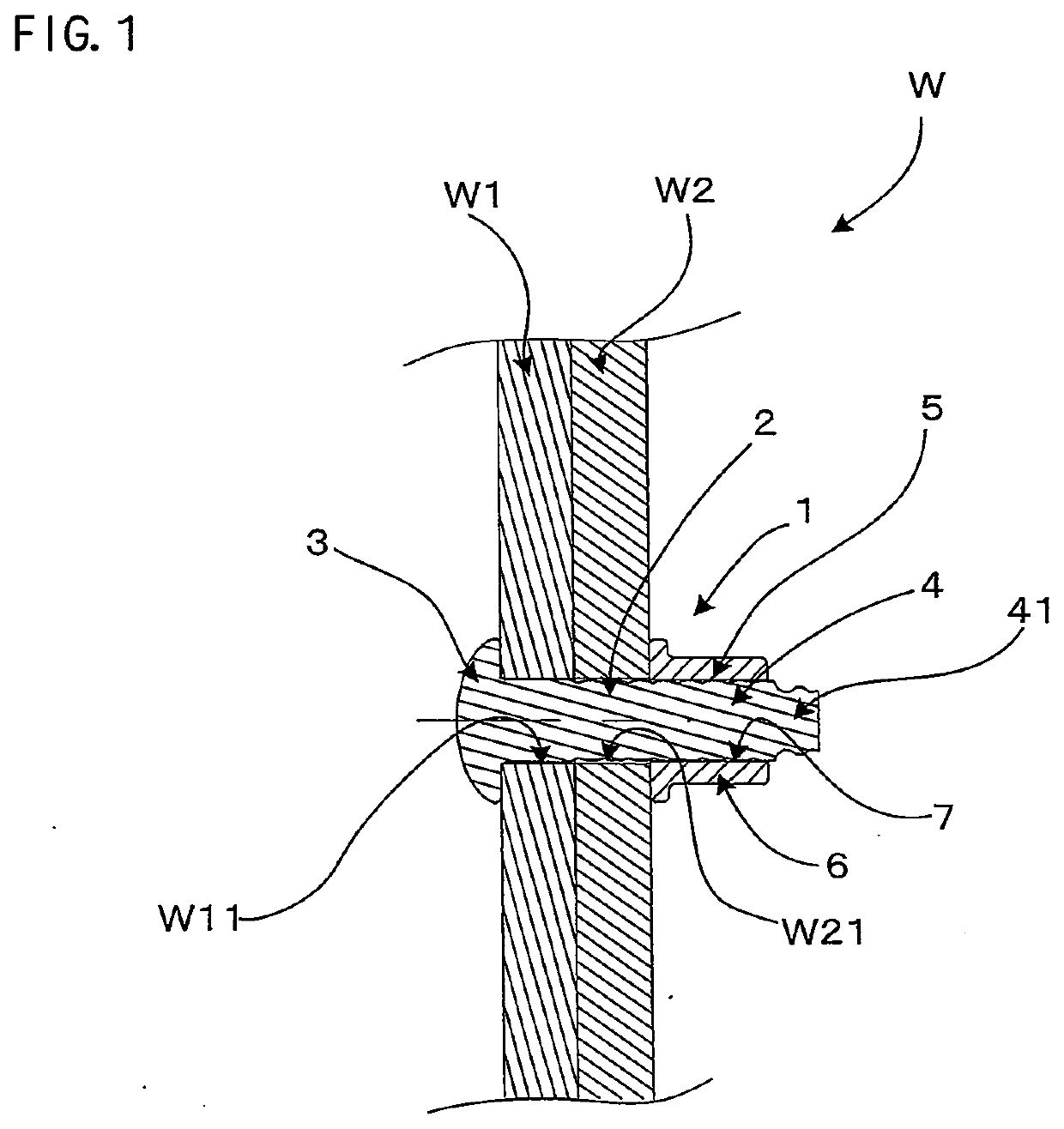
[0056]FIG. 1 shows a workpiece W and a fastener 1 according to an embodiment of the present invention. In the present embodiment, as an example, the workpiece W consists of plate-like metal members W1 and W2 to be fastened. The members W1 and W2 to be fastened are superimposed such that through holes W11 and W21 respectively formed in advance in the members W1 and W2 to be fastened are aligned with each other.

[0057]The fastener 1 mainly includes a bolt 2 and a collar 6. The bolt 2 has a head 3 and a bolt shaft 4. The bolt shaft 4 is integrally formed with the head 3 and has grooves 5 formed in its outer periphery. The head 3 is an example that corresponds to the “head part” according to the present invention. The grooves 5 are formed substantially over the whole length in an axial direction of the bolt shaft 4. The collar 6 has a c...


PUM

PropertyMeasurementUnit
Speedaaaaaaaaaa
Currentaaaaaaaaaa

Abstract

A fastening tool using a fastener of a type which is configured such that swaging is completed while an end region of a shaft part of a bolt remains integrated with the shaft part, and more particularly, a technique that may help provide a compact device structure while facilitating output management required for swaging, in the fastening tool. The fastening tool is configured to fasten a workpiece with a bolt and a collar without breaking a shaft part of the bolt, and a control part performs swaging operation while controlling the driving current of a motor to become a specified target current value and completes the swaging operation based on rotation speed of the motor.

Description

TECHNICAL FIELD[0001]The present invention relates to a fastening tool which uses a fastener including a bolt and a cylindrical hollow collar that is engageable with the bolt, the bolt having a head part integrally formed with a shaft part having a groove, to fasten a workpiece between the head part and the collar.BACKGROUND ART[0002]As for a fastening operation of a workpiece using the fastener configured as described above, two types are known. Firstly, swaging operation may be completed while an end region of the shaft part of the bolt remains integrated with the shaft part. Secondly, swaging operation may be completed while the end region of the shaft part is broken and removed from the shaft part. The former type (first type) may be advantageous in that an additional process of reapplying a coating agent to a broken part can be omitted since the fastening operation is performed without breaking the shaft part. The latter type (second type) may be advantageous in that the fasten...

Claims


Application Information

Patent Timeline
IPC IPC(8): B21J15/26B21J15/10B21J15/28
CPCB21J15/022B21J15/26B21J15/28B21J15/105B21J15/285B21J15/045
Inventor YABUGUCHI, MICHISADAYABUNAKA, TOSHIHITO
Owner MAKITA CORP
Why Eureka
Try Eureka