
Multichannel optical multiplexing device using a single light bandpass filter

a multi-channel optical multiplexing and light bandpass filter technology, applied in the field of optical communication systems, can solve the problems of limited number of channels of different wavelengths that may be mixed into or extracted from light beams, and achieve the effect of reducing the number of light bandpass filters, and compact structure of the multiplexing devi

Inactive Publication Date: 2005-07-05
RAYTHEON CANADA LTD
View PDF14 Cites 0 Cited by
  • Summary
  • Abstract
  • Description
  • Claims
  • Application Information

AI Technical Summary

Benefits of technology

[0006]The present invention provides an optical multiplexing device that is based on the use of the established bandpass filter technology, yet reduces the number of light bandpass filters required to accomplish the mixing or the separation of the channels. Two or more wavelengths of light are mixed to form, or separated from, a light beam using a single light bandpass filter. The physical size of the light bandpass filter need not be increased to handle multiple channels of extraction. The number of channels of different wavelength that may be mixed into or extracted from the light beam is limited by the ability to pack the light source, light receptors, and light receivers around the light bandpass filter, and possibly by heating of the light bandpass filter if the light beam energy is sufficiently high. Reducing the number of light bandpass filters allows the multiplexing device structure to be made more compact, and also reduces the possibility of loss of alignment due to thermal or other effects.
[0012]The present invention is based upon a recognition that the bandpass wavelength of the light bandpass filter is dependent upon the angle of incidence of the light beam upon the light bandpass filter. One channel at one wavelength is extracted by directing the light beam onto the light bandpass filter at the first angle of incidence, and the next channel is extracted by redirecting the beam (with the first channel removed) onto the light bandpass filter at the second angle of incidence. The number of light bandpass filters required for a multiplexing device is thereby reduced, in some cases to only one light bandpass filter. The same principles may be applied in reverse to form a light combiner or multiplexer.

Problems solved by technology

The number of channels of different wavelength that may be mixed into or extracted from the light beam is limited by the ability to pack the light source, light receptors, and light receivers around the light bandpass filter, and possibly by heating of the light bandpass filter if the light beam energy is sufficiently high.

Method used


Image

  • Multichannel optical multiplexing device using a single light bandpass filter
  • Multichannel optical multiplexing device using a single light bandpass filter
  • Multichannel optical multiplexing device using a single light bandpass filter

Examples


Embodiment Construction

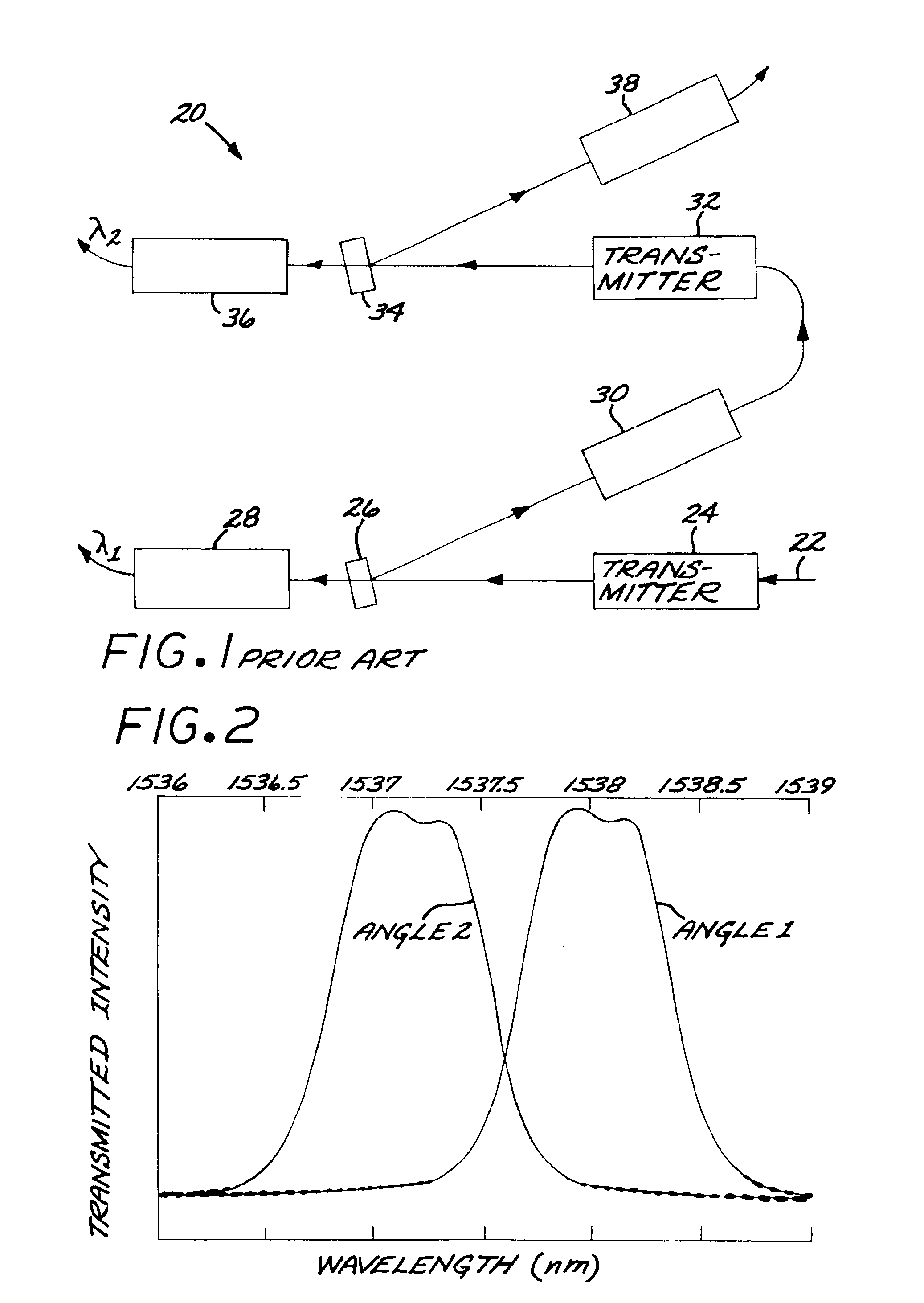
[0019]FIG. 1 depicts a conventional demultiplexer 20 for extracting light of a first wavelength λ1 and light of a second wavelength λ1 from an incoming light beam 22. The demultiplexer 20 includes a first transmitter 24 that directs the light beam 22 onto a first filter 26. The light of wavelength λ1 passes through the first light bandpass filter 26 and is received by a first light receiver 28. The remainder of the beam reflects from the first light bandpass filter 26, is received by a first collimator 30, and is conveyed to a second transmitter 32. The beam is transmitted to a second light bandpass filter 34, where the light of wavelength λ2 is passed through to a second light receiver 36, and the remainder of the beam is reflected from the second light bandpass filter to a second collimator 38. This process is repeated for each of the wavelengths of light to be extracted from the light beam 22, with a suitable light bandpass filter provided for each wavelength that is extracted.

[0...


PUM


Abstract

An optical multiplexing device includes a light bandpass filter that passes a first light wavelength at a first angle of incidence and passes a second light wavelength at a second angle of incidence. In a demultiplexing version, a light source directs a first incident beam including light of the first wavelength and light of the second wavelength at the first angle of incidence onto the light bandpass filter. The light bandpass filter passes the light of the first wavelength therethrough and reflects a first reflected beam therefrom. A first light receptor and redirector receives the first reflected beam and redirects the first reflected beam back onto the light bandpass filter at the second angle of incidence as a second incident beam. The light bandpass filter passes the light of the second wavelength therethrough and reflects a second reflected beam therefrom. The principle may be extended to the demultiplexing of additional wavelengths of light from the incident beam.

Description

[0001]This invention relates to optical communications and, more particularly, to an optical multiplexing device used in an optical communications system.BACKGROUND OF THE INVENTION[0002]In an optical communications system, information is encoded onto a light signal. The light signal is transmitted from one point to another, as for example by free-space light beams or optical fibers. At the receiving end, the information is read from the light signal.[0003]An important advantage of optical communications is that a number of different light signals of different wavelengths may be mixed together (multiplexed) into a single light beam in a technique known as wavelength division multiplexing (WDM). Each light signal of a different wavelength, or channel, has information encoded onto it prior to the mixing of the channels. At the receiving end, the channels are separated, or demultiplexed, according to their wavelengths. The information on each channel is read from the demultiplexed ligh...

Claims


Application Information

Patent Timeline
Patent Type & Authority Patents(United States)
IPC IPC(8): G02B6/293G02B6/34
CPCG02B6/29364G02B6/2938
Inventor LOREGIO, PAUL
Owner RAYTHEON CANADA LTD
Learn More