Magnetic tape device and magnetic tape maintenance method
Active Publication Date: 2017-06-22
NEC PLATFORMS LTD
View PDF23 Cites 11 Cited by
Summary
Abstract
Description
Claims
Application Information
AI Technical Summary
This helps you quickly interpret patents by identifying the three key elements:
Problems solved by technology
Method used
Benefits of technology
Benefits of technology
The present invention relates to a magnetic tape device and a magnetic tape maintenance method. The invention aims to prevent an increase in manufacturing cost and implement a compact structure of the device. The technical effects of the invention prevent the need for expensive components and reduce the size of the device. This results in a more cost-effective and compact magnetic tape device.
Problems solved by technology
If the state that the magnetic tape is stopped continues for a relatively long period of time, the magnetic tape is stuck to the magnetic head due to static electricity or the like.
Method used
Image
Click on the blue label to locate the original text in one second.
Reading with bidirectional positioning of images and text.
Examples
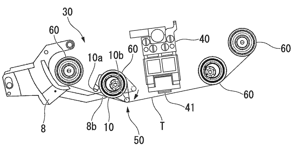
first embodiment
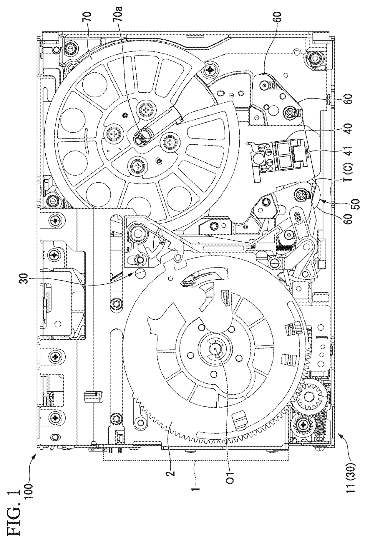
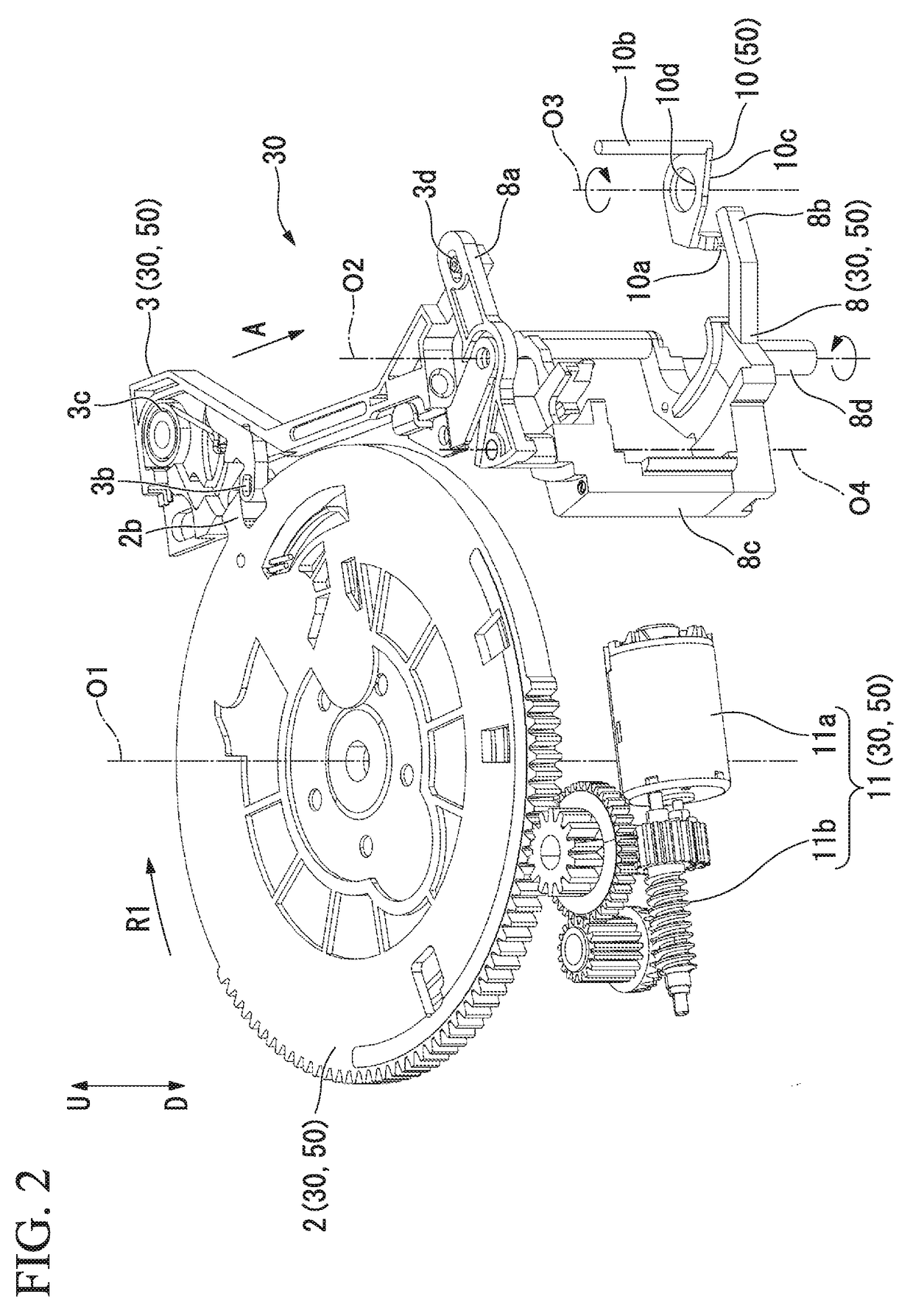
[0030]Below, a magnetic tape device 100 as the present invention will be explained with reference to FIGS. 1 to 5.
[0031]As shown in FIG. 1, the magnetic tape device 100 is utilized as an external storage device when a cartridge 1, which contains a magnetic tape T, is loaded into the device 100.
[0032]The magnetic tape device 100 has a travel unit 30 that pulls out the magnetic tape T contained in the cartridge 1 and moves the magnetic tape T along a travel route C explained later; a magnetic head 40 that performs data reading and writing for the magnetic tape T run by the travel unit 30; and a lifter unit 50 by which when the magnetic tape T is stuck to the magnetic head 40, the magnetic tape T is separated from the magnetic head 40.
[0033]The structure of the travel unit 30 will be explained with reference to FIG. 2. In the following explanation, rotating shafts O1, O2, O3, and O4 extend along an arrow U-D in FIG. 2.
[0034]As shown in FIG. 2, the travel unit 30 has a loader gear 2 whi...
second embodiment
[0094]Next, the present invention will be explained with reference to FIG. 6.
[0095]A magnetic tape device 200 of the present embodiment differs from the above first embodiment as described below.
[0096]That is, the magnetic tape device 200 of the present embodiment has a magnetic tape T which runs on a travel route C, a travel unit 30 that runs the magnetic tape T on the travel route C, a magnetic head 40 that contacts the magnetic tape T to perform data reading and writing, and a lifter unit 50 provided on the travel route C.
[0097]Even such a structure can obtain an effect similar to that obtained by the first embodiment. That is, even when the magnetic tape T is stuck to the magnetic head 40 due to static electricity or the like, such a state can be cancelled by operating the lifter unit 50. Accordingly, the magnetic tape T can appropriately run on the travel route C and data reading and writing on the magnetic tape T can be appropriately performed by the magnetic tape device 200.
[...
PUM
Abstract
A magnetic tape device includes a magnetic tape as a storage medium; a travel unit that moves the magnetic tape along a travel route; a magnetic head that is arranged at the travel route and performs data reading and writing for the magnetic tape that moves on the travel route; and a lifter unit that is arranged at the travel route and contacts the magnetic tape which is stopped on the travel route, where the lifter unit is able to reciprocate in a direction that intersects the travel route so as to separate the magnetic tape from the magnetic head.
Description
TECHNICAL FIELD[0001]The present invention relates to a magnetic tape device and a magnetic tape maintenance method.BACKGROUND ART[0002]As a data storage device utilized to record large quantities of data, a magnetic tape device using a magnetic tape is known, for which “LTO (Linear Tape-Open)” is a representative standard.[0003]Such a magnetic tape device has a structure in which after a cartridge that contains a magnetic tape wound on a reel is loaded into the magnetic tape device, the magnetic tape is pulled out from the cartridge so as to read and write data. The reading and writing of data is performed by running the magnetic tape while the magnetic tape contacts a magnetic head provided in the magnetic tape device.[0004]While no data reading or writing of the magnetic tape is performed, the magnetic tape is stopped. If the state that the magnetic tape is stopped continues for a relatively long period of time, the magnetic tape is stuck to the magnetic head due to static electr...
Claims
Application Information
Patent Timeline
Application Date:The date an application was filed.
Publication Date:The date a patent or application was officially published.
First Publication Date:The earliest publication date of a patent with the same application number.
Issue Date:Publication date of the patent grant document.
PCT Entry Date:The Entry date of PCT National Phase.
Estimated Expiry Date:The statutory expiry date of a patent right according to the Patent Law, and it is the longest term of protection that the patent right can achieve without the termination of the patent right due to other reasons(Term extension factor has been taken into account ).
Invalid Date:Actual expiry date is based on effective date or publication date of legal transaction data of invalid patent.

