
Magnetic head and information storage device

Inactive Publication Date: 2008-03-06
FUJITSU LTD
View PDF6 Cites 0 Cited by
  • Summary
  • Abstract
  • Description
  • Claims
  • Application Information

AI Technical Summary

Benefits of technology

[0014]The invention has been made in view of the above circumstances and provides a magnetic head and an information storage device which can suppress an increase in manufacturing costs and achieve both the inhibition of the pole erase and side erase and an increased recording density.

Problems solved by technology

However, the technique described in Japanese Patent Laid-Open No. 2004-281023 considerably limits the combination of the ferromagnetic material (for example, FeCo) and nonmagnetic material (for example, Ru) constituting the main magnetic pole.
For example, if the main magnetic pole is produced by combining FeCo and Ru, a plating method, which is economically excellent and suitable for mass production, cannot be used to stack these layers.
As a result, the stacking method is almost limited to a sputtering method, unfortunately increasing manufacturing costs.
Further, the side erase cannot be sufficiently inhibited by using the techniques described in Japanese Patent Laid-Open Nos. 2004-281023 and 2003-242608.

Method used


Image

  • Magnetic head and information storage device
  • Magnetic head and information storage device
  • Magnetic head and information storage device

Examples


example

[0072]An example of the invention will be described.

[0073]FIG. 8 is a graph showing the saturation magnetic flux densities and coercive forces of various magnetic materials conventionally widely used for the main magnetic pole.

[0074]In FIG. 8, the axis of abscissa is associated with the saturation magnetic flux density Bs [T]. The axis of ordinate is associated with the coercive force Hc [A / m]. CoNiFe-containing magnetic materials are plotted with circles. NiFe-containing materials are plotted with squares. FeCo-containing materials are plotted with rhombuses.

[0075]Normally, to inhibit the pole erase, the main magnetic pole needs to offer a coercive force Hc of at most 500 [A / m]. Further, to increase the recording density, the main magnetic pole needs to offer a saturation magnetic flux density Bs of at least 2.1 [T].

[0076]Disadvantageously, as shown in FIG. 8, the NiFe-containing materials (plotted with squares) offer coercive forces Hc of at most 500 [A / m] but too low saturation m...


PUM


Abstract

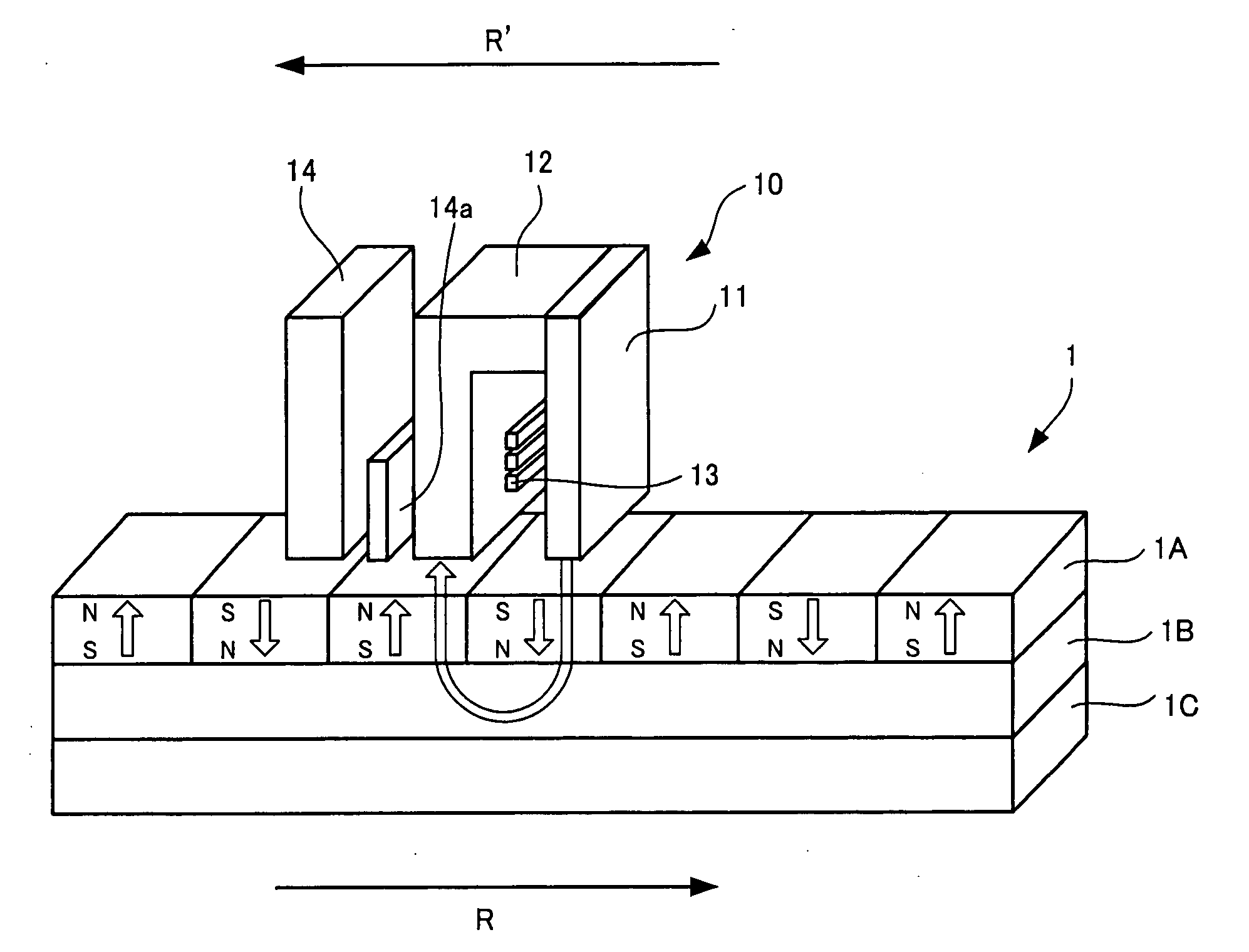
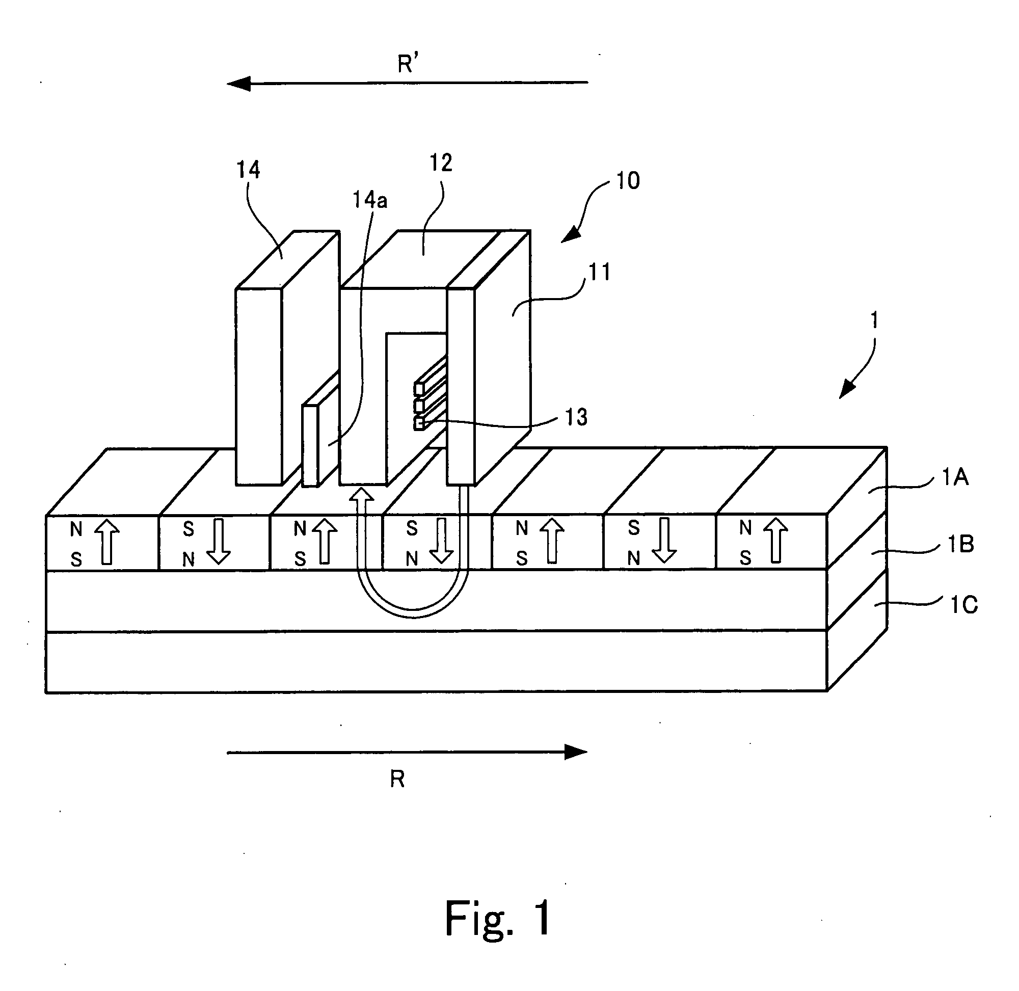
A magnetic head includes a magnetic pole placed opposite a surface of a recording medium and moving relatively to the surface in a direction along the surface, the magnetic pole generating a magnetic line of force that crosses the surface of the recording medium, and a coil that excites the magnetic pole. The magnetic pole has a number of layers stacked on one another in a direction along the movement relatively to the surface of the recording medium, and the layers include a most forward layer located at a most forward position of the movement and consisting of a first magnetic material and a most backward layer located at a most backward position of the movement and consisting of a second magnetic material having a saturation magnetic flux density higher than that of the first magnetic material and a coercive force larger than that of the first magnetic material.

Description

BACKGROUND OF THE INVENTION[0001]1. Field of the Invention[0002]The present invention relates to magnetic heads that apply magnetic fields to recording media and information storage devices that use magnetic fields to access information in recording media.[0003]2. Description of the Related Art[0004]The advancement of information societies has been continuously increasing the amount of information used. To deal with the increased amount of information used, it has been desirable to develop information recording technologies and information storage devices for significantly high recording densities. In particular, magnetic disks to which information accesses can be made using magnetic fields are gathering much attention as high-density recording media that allow information to be rewritten. Many researches and developments have been carried out to achieve, for example, a further increased recording density.[0005]An in-surface recording technology for magnetizing a recording medium in...

Claims


Application Information

Patent Timeline
IPC IPC(8): G11B5/127
CPCG11B5/1278G11B5/147G11B5/3116G11B5/3109G11B5/1872G11B5/31G11B5/66Y10S428/90
Inventor MIYAKE, YUKOMATSUOKA, MASAAKI
Owner FUJITSU LTD
Learn More