Refrigerant compressor provided with a sound damper for an air condtioning unit

Inactive Publication Date: 2008-03-20
VISTEON GLOBAL TECH INC
View PDF10 Cites 1 Cited by
  • Summary
  • Abstract
  • Description
  • Claims
  • Application Information

AI Technical Summary

Benefits of technology

[0006]In DE 100 11 023 A1, a muffler for a connection to a pressure outlet of a compressor is disclosed. A partition wall is disposed between a bottom wall and a top wall dividing an interior of a casing into an inflow chamber and an outflow chamber. The partition wall includes a passage zone having several small holes. Parallel to the partition wall, a passage zone is at a distance to an inflow opening and an outflow opening. The partition wall is disposed such that a gaseous medium delivered by the compressor flows from the inflow opening through the inflow chamber to the passage zone and from the passage zone through the outflow chamber to the outflow opening.
[0007]A particular disadvantage of the muffler as an external component is the amount of assembly space for disposition of the compressor. In addition, the muffler can only be used on the high pressure side of the compressor.
[0008]Further, in U.S. Pat. No. 3,577,891, a swash plate compressor is disclosed having a muffler on a high-pressure side. The muffler comprises a stilling chamber into which a pipe leads which is established as a separate component and is provided with holes for a refrigerant. The pipe is disposed in a portion of the high-pressure channel. Two disadvant

Problems solved by technology

A disadvantage of the invention is that the diffuser is an insert that has to be manufactured separately, which increases manufacturing costs and may cause incorrect flow in a sealing region of the suction or the pressure connections.
A particular disadvantage of the muffler as an external component is the amount of assembly space for disposition of the compressor.
In addition, the muffler can only be used on the high pressure side of the compressor.
Two disadvantages o

Method used


Image

  • Refrigerant compressor provided with a sound damper for an air condtioning unit
  • Refrigerant compressor provided with a sound damper for an air condtioning unit
  • Refrigerant compressor provided with a sound damper for an air condtioning unit

Examples


Example

[0038]The following detailed description and appended drawings describe and illustrate various exemplary embodiments of the invention. The description and drawings serve to enable one skilled in the art to make and use the invention, and are not intended to limit the scope of the invention in any manner.

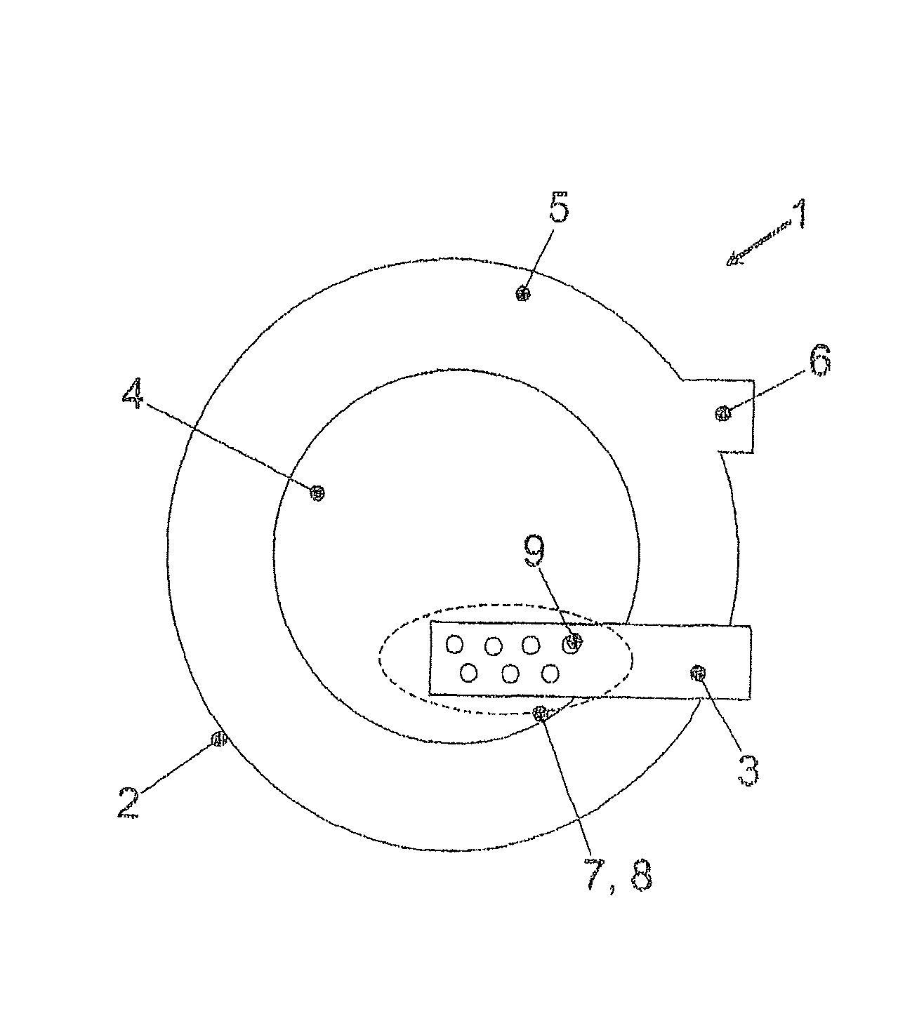
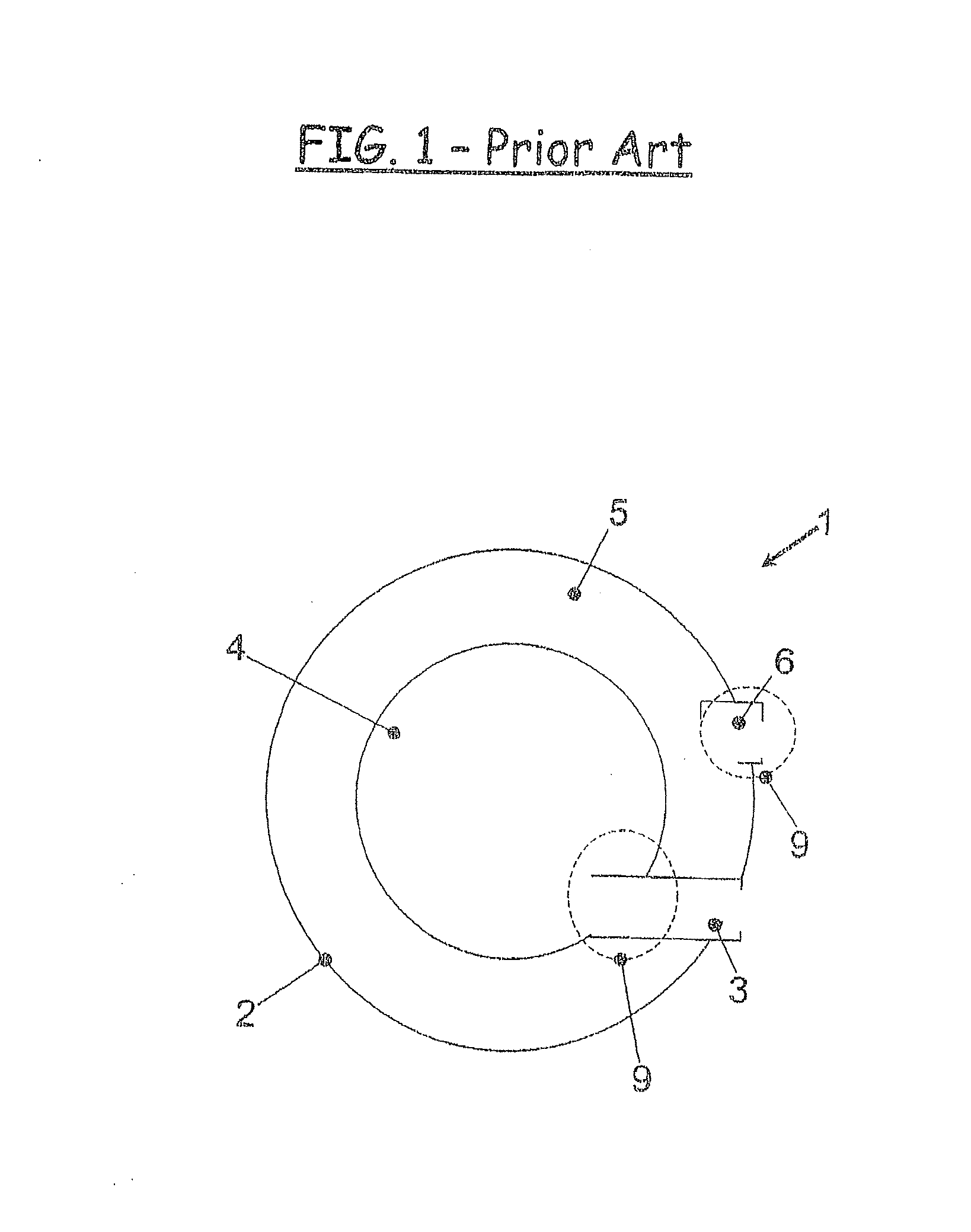
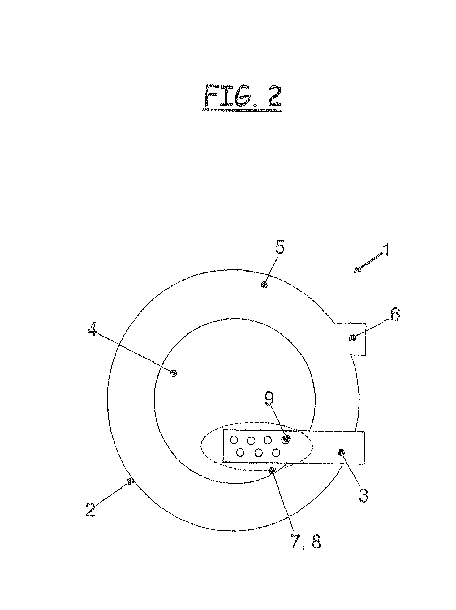
[0039]FIG. 1 shows a refrigerant compressor 1 of prior art. The refrigerant compressor 1 includes a casing 2, an inlet channel 3 leading into a inlet chamber 4 having a generally circular cross-sectional shape, an outlet chamber 5 having a generally annular cross-sectional shape surrounding the inlet chamber 4, and an outlet channel 6 which in a direction of a flow of a compressed refrigerant is disposed subsequently to the outlet chamber 5.

[0040]As clearly shown in FIG. 1, the inlet channel 3 having a substantially uniform cross-section is formed to extend through the outlet chamber 5. The refrigerant flows into the inlet chamber 4 passing through a face-side opening, or through an ...


PUM


Abstract

The invention relates to a refrigerant compressor provided with a muffler for an air conditioning unit in a vehicle, wherein the refrigerant compressor includes a swash plate or pivoting ring rotatably supported in a casing of the refrigerant compressor for driving axially moving pistons arranged in cylinders, a suction side provided with an inlet channel and an inlet chamber, and a pressure side provided with an outlet channel and an outlet chamber. The muffler including a partition wall having a plurality of apertures formed therein is disposed in at least one of the suction side and the outlet side of the casing.

Description

CROSS-REFERENCE TO RELATED APPLICATION[0001]This application claims priority to German Patent Application Serial Number 102006044821.9-15, filed Sep. 14, 2006, the entire disclosure of which is hereby incorporated herein by reference.FIELD OF THE INVENTION[0002]The invention relates to a refrigerant compressor provided with a muffler for an air conditioning unit in a vehicle, and more particularly to a muffler including a partition wall having a plurality of apertures formed therein.BACKGROUND OF THE INVENTION[0003]In vehicles, mufflers are used in order to damp noise, especially noise caused by pressure pulsations. The process of compression of a refrigerant such as CO2, for example, in a compressor causes pressure pulsations which can be transmitted to an air conditioning unit over an inlet and an outlet of the compressor. The pressure pulsations can be perceived as unwanted noise in an interior of a vehicle by occupants of the vehicle.[0004]In practice, different structures are u...

Claims


Application Information

Patent Timeline
IPC IPC(8): F25D19/00F04B39/00
CPCF04B27/1081F04B39/125F04B39/0055
Inventor SCHILLEMEIT, BALTHASAR
Owner VISTEON GLOBAL TECH INC
Why Eureka
Try Eureka