

Telescoping, uncoupling lever and glide housings for a railroad car
- Summary
- Abstract
- Description
- Claims
- Application Information
AI Technical Summary
Benefits of technology
Problems solved by technology
Method used
Image

Examples
Embodiment Construction
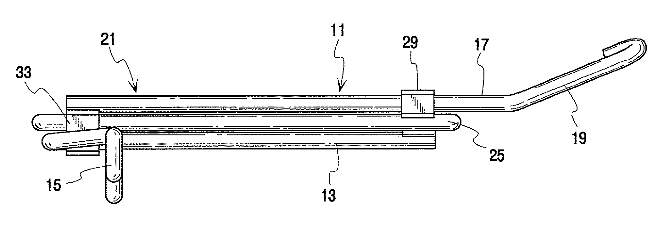
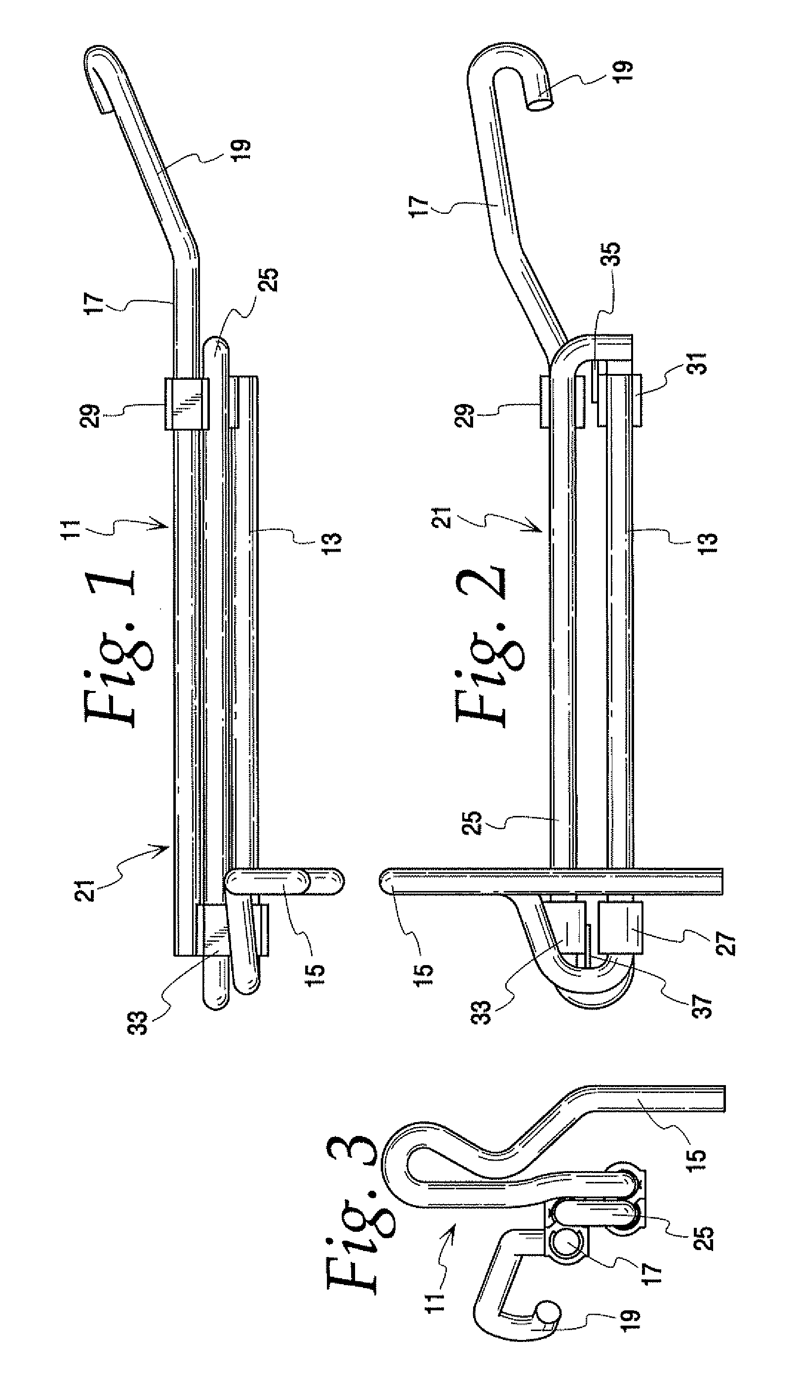
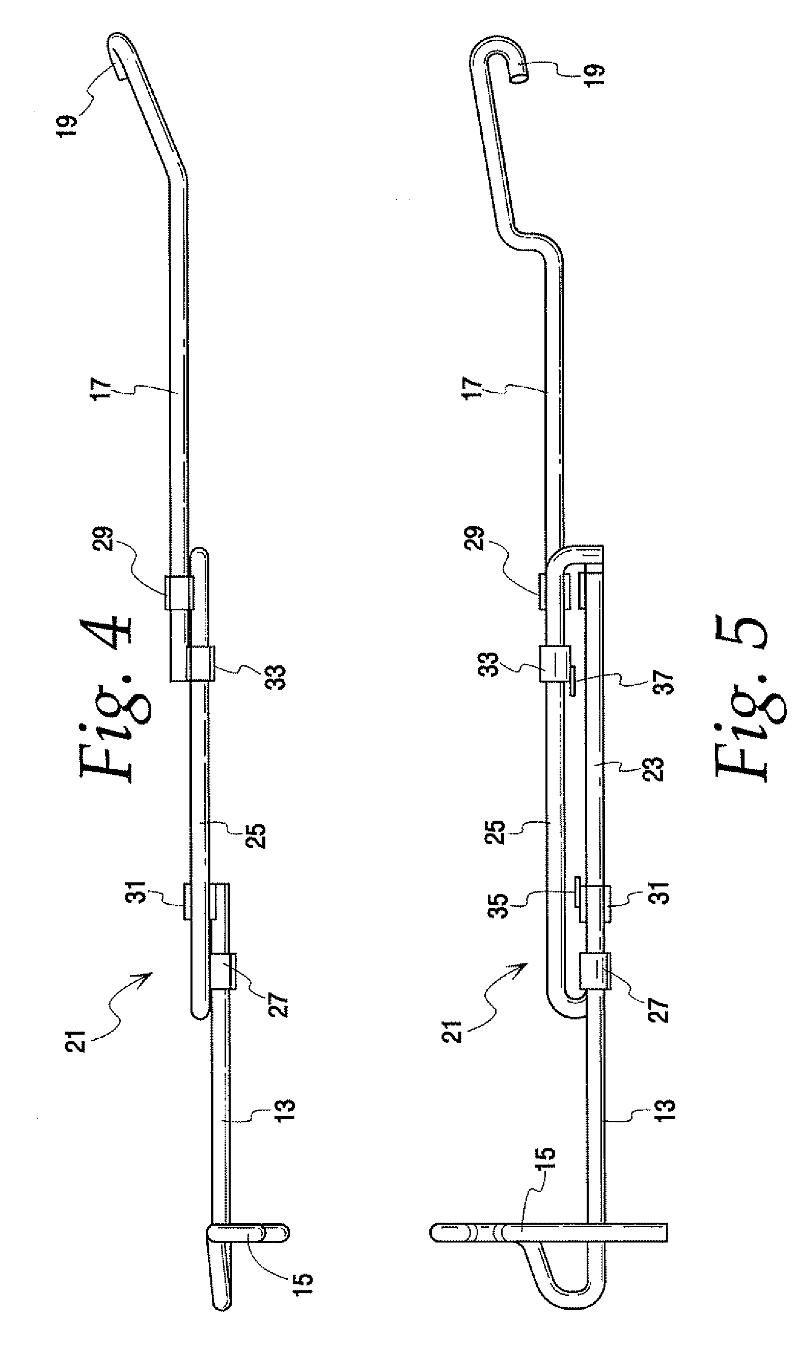
[0021]FIGS. 1-5 of the drawings are views of a telescoping, uncoupling lever 11 of this invention which is intended to be mounted on an end of a railroad freight car. The telescoping, uncoupling lever 11 includes a handle rod 13 having an integral handle 15, a lock lifter rod 17 having an integral lock lifter 19 and a track assembly 21. The track assembly 21 includes a handle rod track 23 and a lock lifter rod track 25. Each of these elements of the telescoping, uncoupling lever, the handle rod lock lifter rod and track assembly are formed from one piece, one inch diameter round bar stock. The use of one inch diameter steel round bar stock for all elements of the uncoupling lever 11 eliminates the need for the more expensive rectangular bar stock used in previous telescoping, uncoupling levers. This new construction also eliminates the need to weld round bar stock handles to rectangular bar stock and does away with the possibility of failure at the welded joints. The handle rod trac...
PUM
 Abstract
Description
Claims
Application Information