Electric device and motor driving device

Active Publication Date: 2019-07-25
FANUC LTD
View PDF7 Cites 0 Cited by
  • Summary
  • Abstract
  • Description
  • Claims
  • Application Information

AI Technical Summary

Benefits of technology

[0004]According to the technique described in Japanese Laid-Open Patent Publication No. 2005-243742, it is necessary to ensure an area for the provision of the short bar

Problems solved by technology

According to the technique described in Japanese Laid-Open Patent Publication No. 2005-243742, it is necessary to ensure an area for the provision of the short bars o

Method used


Image

  • Electric device and motor driving device
  • Electric device and motor driving device

Examples


first embodiment

[Configuration of Motor Driving Device]

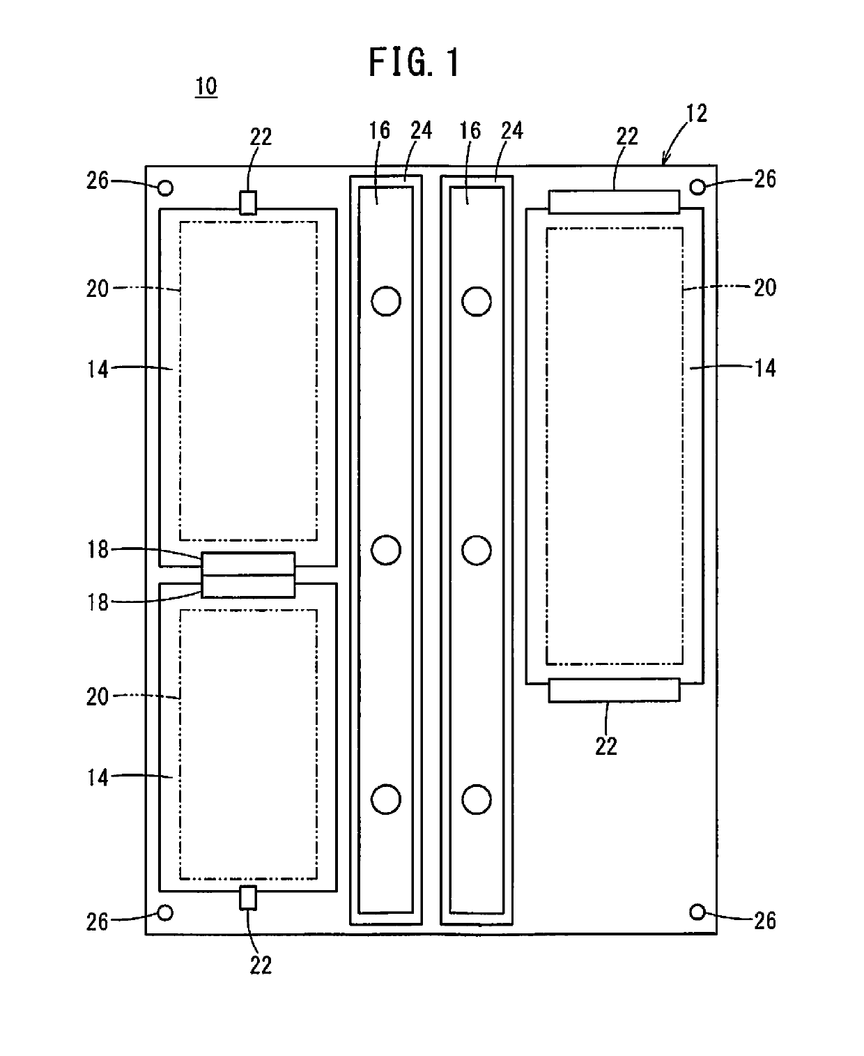
[0011]FIG. 1 is a schematic diagram showing the internal structure of a motor driving device 10. The motor driving device 10 is a device which controls electric power supplied to a motor not shown. The motor driving device 10 includes a resin board 12, printed boards 14 provided on the resin board 12, and short bars 16 also provided on the resin board 12.

[0012]The resin board 12 is a plate-shaped member produced by injection molding of a resin material. The printed boards 14 are plate-shaped members produced by printing a pattern on a stack of laminated plates formed of resin.

[0013]Mounted on the printed boards 14 are control units 20 composed of a plurality of electronic elements and configured to control power supplied to the motor, connectors 18 for making electrical connections with other printed boards 14, and so on. The short bars 16 are connected to a power device (not shown), and a current larger than a current passed through the contro...


PUM


Abstract

A motor driving device includes a printed board on which a pattern is printed, and a resin board which is formed by molding a resin and on which no pattern is printed, and the printed board is provided on the resin board.

Description

CROSS-REFERENCE TO RELATED APPLICATION[0001]This application is based upon and claims the benefit of priority from Japanese Patent Application No. 2018-006951 filed on Jan. 19, 2018, the contents of which are incorporated herein by reference.BACKGROUND OF THE INVENTIONField of the Invention[0002]The present invention relates to an electric device and a motor driving device having a printed board on which a pattern is printed.Description of the Related Art[0003]Japanese Laid-Open Patent Publication No. 2005-243742 discloses a motor driving device in which short bars are mounted on a printed board.SUMMARY OF THE INVENTION[0004]According to the technique described in Japanese Laid-Open Patent Publication No. 2005-243742, it is necessary to ensure an area for the provision of the short bars on the printed board, and thus enlarging the area of the printed board, whose unit price per area is high, may increase manufacturing costs of the motor driving device.[0005]The present invention has...

Claims


Application Information

Patent Timeline
IPC IPC(8): H05K7/14H05K1/14H05K1/18H05K3/36H05K1/02
CPCH05K7/1427H05K1/14H05K1/18H05K3/36H05K1/0263H05K2201/09818H05K7/06H05K2201/10409H05K2201/10272H05K1/142H05K3/0064H05K7/14322H05K7/1432
Inventor HORIKOSHI, SHINICHINAKAGAWA, YUUYA
Owner FANUC LTD
Why Eureka
Try Eureka