

Buckle of a belt
- Summary
- Abstract
- Description
- Claims
- Application Information
AI Technical Summary
Benefits of technology
Problems solved by technology
Method used
Image

Examples
embodiment 1
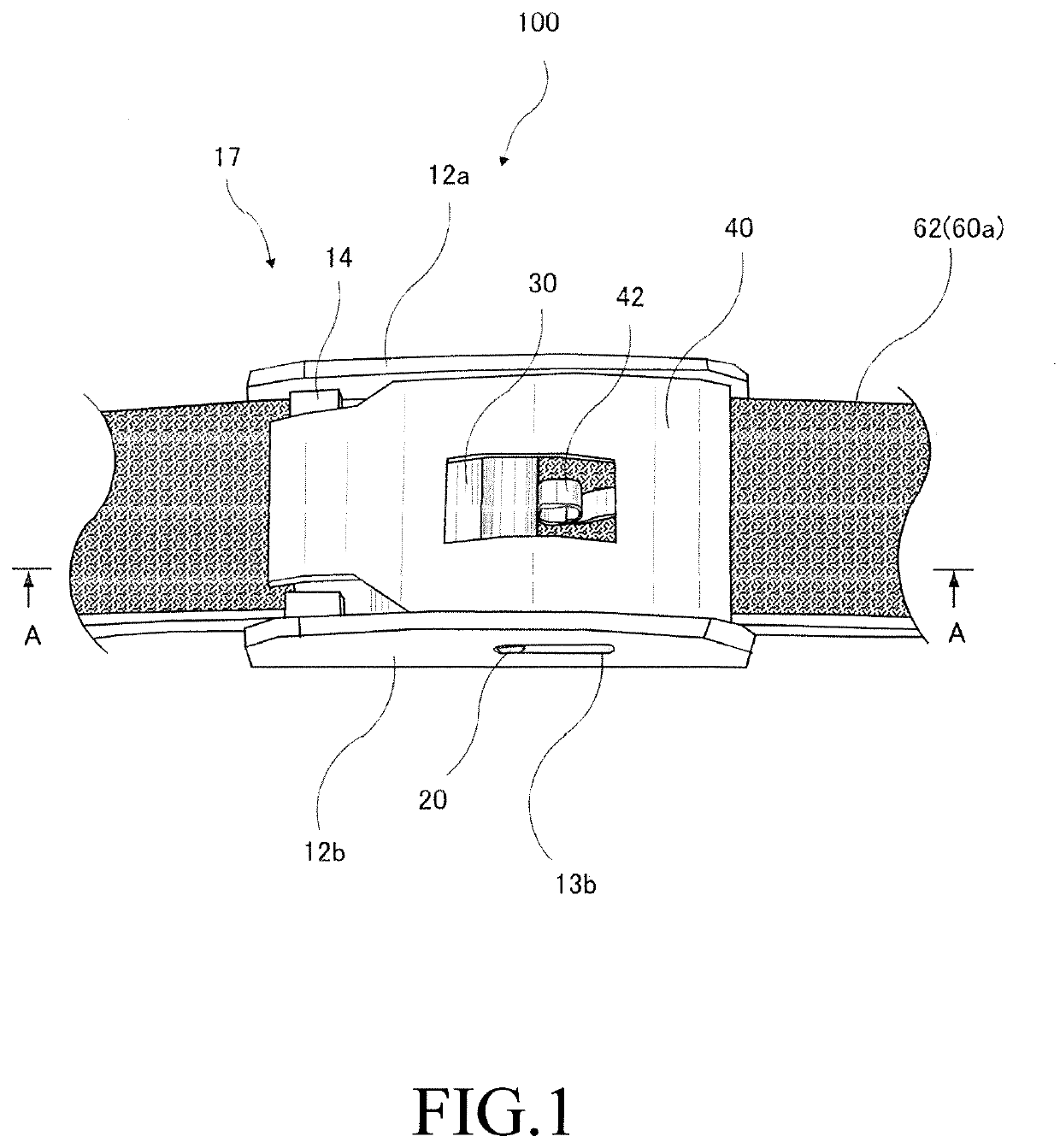
[0044]FIG. 1 is a perspective view as viewed from the front direction, which illustrates an example of the configuration of a buckle for a clothing belt according to Embodiment 1. The rotating body rotates around the shaft in a case where the shaft is fixed to the base body and the shaft rotates in the base body in a case where the shaft is fixed to the rotating body.
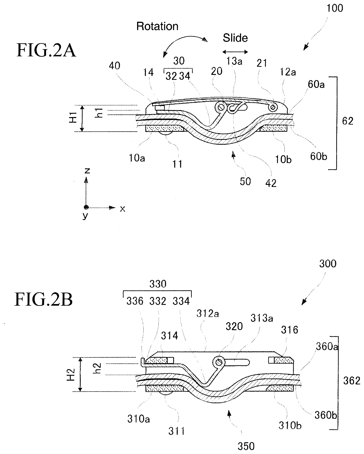
[0045]FIG. 2A is a diagram illustrating an example of the cross-sectional configuration of the buckle for a clothing belt according to Embodiment 1 as viewed from the bottom surface direction. FIG. 2B is a diagram illustrating an example of the cross-sectional configuration of a buckle for a clothing belt according to a first comparative example as viewed from the bottom surface direction. Illustrated in FIG. 2A is a cross section of the buckle for a clothing belt according to Embodiment 1. Illustrated in FIG. 2B is a cross section of the first comparative example, in which the other end side of a clasp of the buckle fo...
embodiment 2
[0067]Described in Embodiment 1 is a configuration in which a force against reverse rotation of the clasp fixture 40 is applied by the clasp fixture 40 being rotated such that the convex portion 42 of the clasp fixture 40 is further pushed in while abutting the convex portion 42 against the shaft side end portion of the belt clasp 30 that moves with the sliding of the shaft 20. However, configurations for application of the force against the reverse rotation of the clasp fixture 40 are not limited thereto.
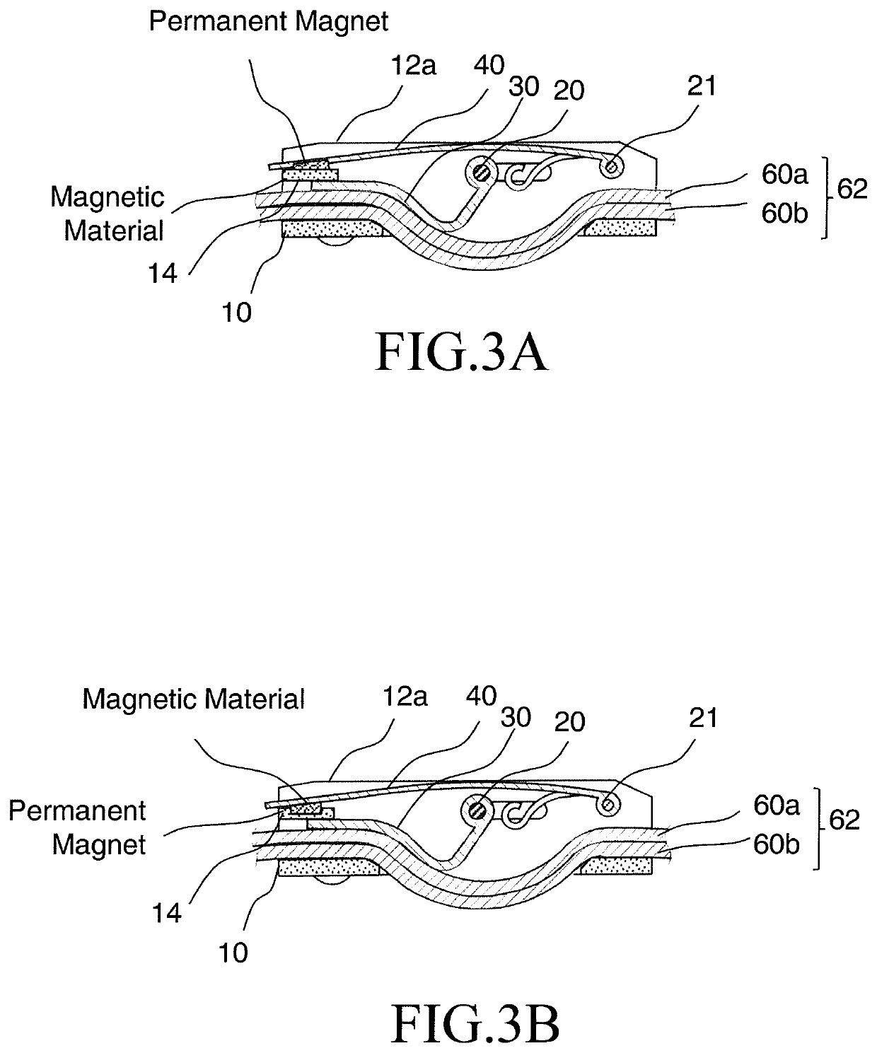
[0068]FIGS. 3A and 3B are diagrams illustrating an example of the cross-sectional configuration of a buckle for a clothing belt according to Embodiment 2 as viewed from the bottom surface direction. A perspective view seen from the front direction and illustrating an example of the configuration of the buckle for a clothing belt according to Embodiment 1 is substantially identical to FIG. 1 except for the bar 14. FIG. 3A illustrates a case where a permanent magnet is disposed on th...
embodiment 3
[0070]FIG. 4 is a diagram illustrating an example of the cross-sectional configuration of a buckle for a clothing belt according to Embodiment 3 as viewed from the bottom surface direction. A perspective view seen from the front direction and illustrating an example of the configuration of the buckle for a clothing belt according to Embodiment 1 is substantially identical to FIG. 1 except for the position of the shaft 21. The shaft 21 is also used as the bar 14 in the example of FIG. 4.
[0071]In FIGS. 1 and 4, the buckle 100 for a clothing belt (hereinafter, referred to as the buckle 100) is provided with the base body 17 of the buckle having the back plate 10 (10a and 10b) and the side plates 12a and 12b, the shaft 20 (first shaft), the belt clasp 30, the shaft 21 (second shaft), and the clasp fixture 40. The slit 50 (opening portion) is formed between the back plates 10a and 10b in the back plate 10. The slit 50 is opened with a width larger than the width of the clothing belt 62 (...
PUM
 Abstract
Description
Claims
Application Information