System for sealing a shaft

Inactive Publication Date: 2013-04-18
GENERAL ELECTRIC CO
View PDF7 Cites 4 Cited by
  • Summary
  • Abstract
  • Description
  • Claims
  • Application Information

AI Technical Summary

Benefits of technology

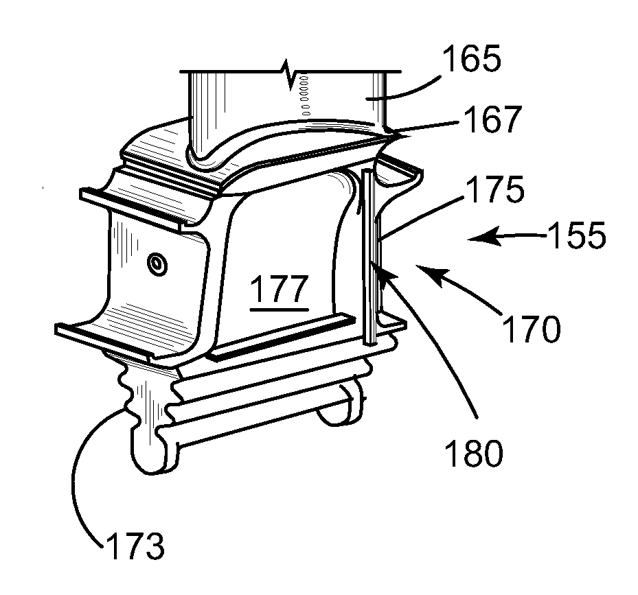
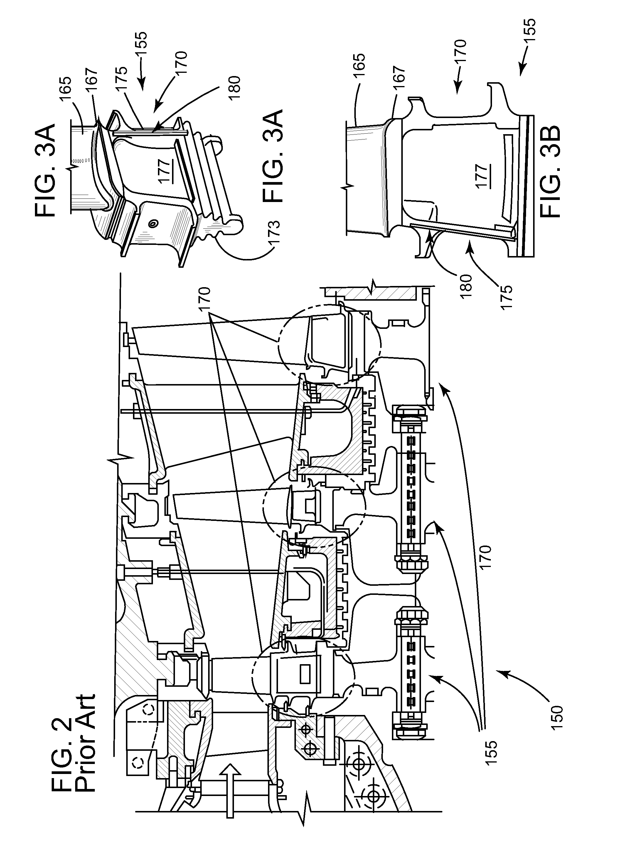
[0006]In accordance with a first embodiment of the present invention, a system comprising: a rotatable component comprising: an airfoil portion comprising a first end, an opposite second end, and suction and pressure surfaces located between the first end and the opposite second end; a shank portion comprising a mount and a slot, wherein the slot is positioned near a wall and is adjacent a downstream edge of the airfoil portion; a platform portion that connects the airfoil portion to the shank portion; a seal comprising: an arm portion; and a hook portion; wherein the arm and hook portions are shaped to mate with the slot such that the slot restrains the movement of the seal; wherein the seal is sized to substantially prevent a cooling flow from leaking through a shank pocket.
[0007]In accordance with a second embodiment of the present invention, a system comprising: a gas turbine compri

Problems solved by technology

In addition, fluid flowing over the platform can leak into the shank pocket.
These sou

Method used


Image

  • System for sealing a shaft
  • System for sealing a shaft
  • System for sealing a shaft

Examples


Example

[0016]One or more specific embodiments of the present invention will be described below. In an effort to provide a concise description of these embodiments, all features of an actual implementation may not be described in the specification. It should be appreciated that in the development of any such actual implementation, as in an engineering or design project, numerous implementation-specific decisions are made to achieve the specific goals, such as compliance with system-related and / or business-related constraints, which may vary from one implementation to another. Moreover, it should be appreciated that such effort might be complex and time consuming, but would nevertheless be a routine undertaking of design, fabrication, and manufacture for those of ordinary skill having the benefit of this disclosure.

[0017]Detailed example embodiments are disclosed herein. However, specific structural and functional details disclosed herein are merely representative for purposes of describing ...


PUM


Abstract

An embodiment of the present invention takes the form of a seal that may substantially reduce cross-shank leakage between components mounted on a shaft. Embodiments of the seal may be connected to a wide variety of rotatable components including, but not limited to, compressor blades, turbine buckets, or the like.

Description

BACKGROUND OF THE INVENTION[0001]The present invention relates to seals for air-ingesting turbomachines; and more particularly to a seal for the shank region of a rotating component of the turbomachine.[0002]Conventional turbomachines includes compressor and turbine sections that each has a plurality of rotating components (compressor blades, turbine components, etc) attached about a circumference of a turbine rotor. Each rotating component is located at a distance away from an adjacent rotating component to allow movement and expansion during operation. Each rotatable component includes: a shank that attaches to the rotor, a platform, and an airfoil that extends radially outwardly from the platform.[0003]The area between the adjacent rotating components is considered the shank pocket. Generally, the cavities between the rotating components and adjacent stationary components forward and aft of the shank pocket are at different operating pressures. Fluid naturally flows from the high...

Claims


Application Information

Patent Timeline
IPC IPC(8): F01D5/30
CPCF01D11/006
Inventor AMARAL, SERGIO DANIEL MARQUESITZEL, GARY MICHAELZHANG, XIUZHANG JAMESMOORE, KENNETH DALE
Owner GENERAL ELECTRIC CO
Why Eureka
Try Eureka