
Belt buckle structure

a belt buckle and buckle technology, applied in the direction of belts, garment fasteners, buckles, etc., can solve the problems of hard releasing and adjusting of belts, complicated structure, inconvenience of operation, etc., and achieve the effect of improving the overall structure, protecting the overall structure, and disengaging

Active Publication Date: 2019-12-05
CHEN HSI HSIN
View PDF10 Cites 0 Cited by
  • Summary
  • Abstract
  • Description
  • Claims
  • Application Information

AI Technical Summary

Benefits of technology

The present invention is a belt buckle structure that includes a plate-based controller integrated into the buckle body. This controller is enclosed and protected by internal recess and protruding section of a fixing member fitted into the coupling section. A pivot pin and primary constraint frame attach the buckle body to two sides, making all parts concealed and improving both protectability and aesthetics. This structure reduces the number of connecting parts, simplifies assembly, and improves overall protection and appearance.

Problems solved by technology

Such an adjustment structure is affected by the size of the buckle and is usually made up of tiny parts, which makes operation inconvenient and often cause over-tight fastening, eventually leading to hard releasing and adjusting of the belt.
Although belt manufacturers have later proposed improvements for such issues of inconvenience, those improvements generally focus on regulation or adjustment speed and easy operation and require an increase of parts of the belt buckles that also complicate the structure.
Consequently, failure and inconvenience of operation may result due to certain tiny parts.
Apparently, the direction of force application is not of a design of ergonomics and as such, over application of force may readily occur, leading to damages.
In practical uses, adjustment of such a belt catch holder (2) is in fact not convenient for users.

Method used


Image

  • Belt buckle structure
  • Belt buckle structure
  • Belt buckle structure

Examples


Embodiment Construction

[0020]The following descriptions are exemplary embodiments only, and are not intended to limit the scope, applicability or configuration of the invention in any way. Rather, the following description provides a convenient illustration for implementing exemplary embodiments of the invention. Various changes to the described embodiments may be made in the function and arrangement of the elements described without departing from the scope of the invention as set forth in the appended claims.

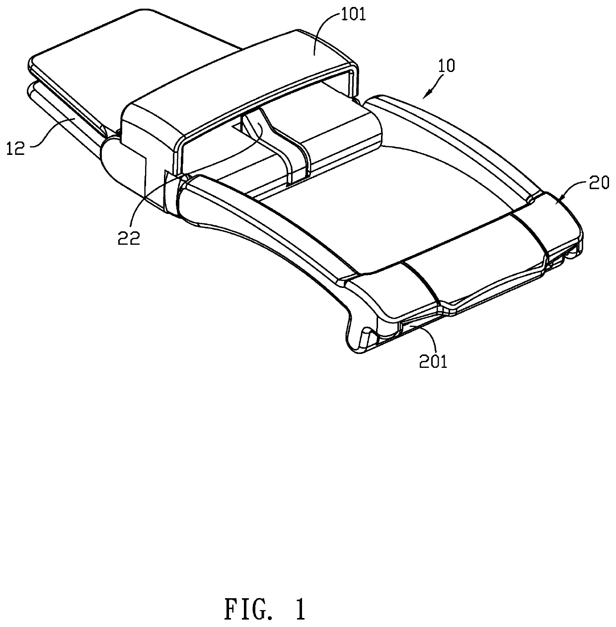
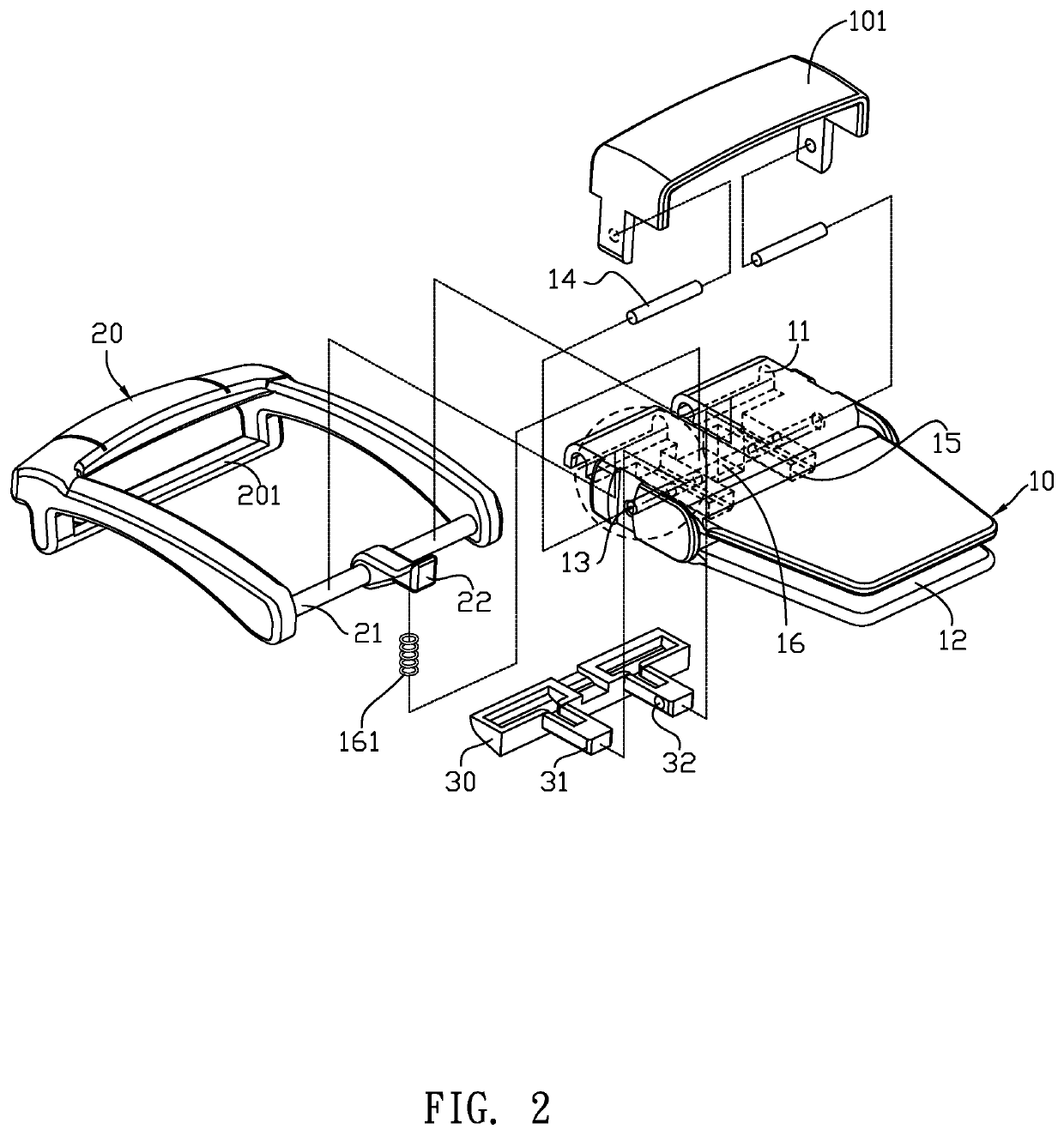
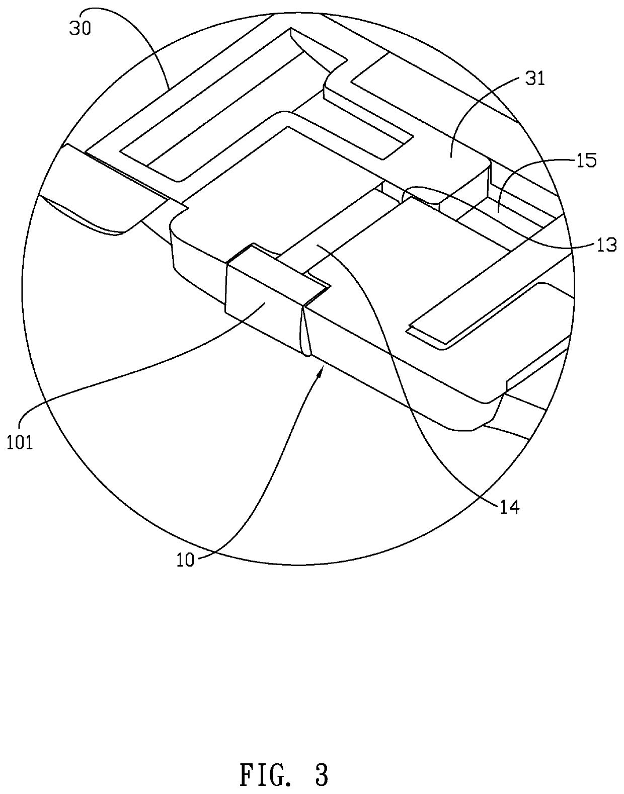
[0021]The present invention provides a belt buckle structure, which, as shown in FIGS. 1-3, comprises: a buckle body 10 and a plate-based controller 20. The buckle body 10 has a front end that is provided with a coupling section 11 and a rear end that is provided with a connection section 12 that is connectable to a belt 40. The coupling section 11 is formed, in a central portion of a top side thereof, with a pivoting notch 16, and the coupling section 11 is also formed, in an internal portion of a ...


PUM


Abstract

A belt buckle structure includes a buckle body and a plate-based controller. The buckle body is provided with a coupling section and a connection section at two ends thereof The coupling section is formed with a pivoting notch in a top side and a recess in a bottom side. A pin hole is formed in each of two sides of the buckle body. The plate-based controller includes a coupling axle having a pawl. The coupling axle is arranged in the coupling section. A fixing member has a protruding section fit into the recess. A pin is received through the pint hole to penetrate through the recess and extend into a positioning hole of the fixing member. A primary constraint frame has two side portions collaborating with the pin to attach to two sides of the buckle body.

Description

CROSS-REFERENCE TO RELATED APPLICATION[0001]This is a continuation-in-part of co-pending U.S. patent application Ser. No. 15 / 937,854 filed on Mar. 27, 2018.(a) TECHNICAL FIELD OF THE INVENTION[0002]The present invention relates generally to a belt buckle structure.(b) DESCRIPTION OF THE PRIOR ART[0003]Two styles of belt are commonly used, which are respectively prong clasping style and automatic fastening style. The automatic fastening style uses a pawl provided on a buckle to engage teeth formed in a toothed strap to achieve fastening of the belt so as to enable a user to wear and use.[0004]The buckle of the automatic fastening style belt that is currently available in the market often involves, in the structure thereof, a button or handle for pressing or pulling to release the pawl for adjustment of the fastening location of the belt. Such an adjustment structure is affected by the size of the buckle and is usually made up of tiny parts, which makes operation inconvenient and ofte...

Claims


Application Information

Patent Timeline
IPC IPC(8): A44B11/12
CPCA44B11/12A41F1/008A44B11/14A44B11/226
Inventor CHEN, HSI-HSIN
Owner CHEN HSI HSIN
Learn More