Plant holder

Inactive Publication Date: 2019-12-26
UNIVERSITY OF ALABAMA
View PDF0 Cites 1 Cited by
  • Summary
  • Abstract
  • Description
  • Claims
  • Application Information

AI Technical Summary

Benefits of technology

[0006]In some implementations, the at least one wal

Problems solved by technology

Traditional vases for holding plants do not allow easy access to stems and require the originally designed plant bouquet to be removed and disturbed to change the water and cut the stems.
In applica

Method used


Image

  • Plant holder
  • Plant holder
  • Plant holder

Examples


Example

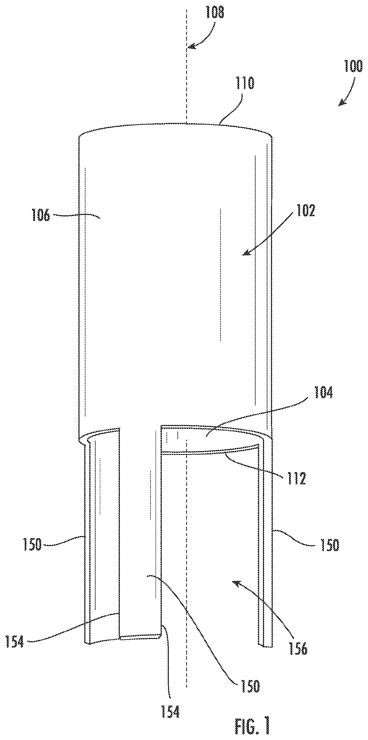
[0041]Various implementations include a plant holder that includes at least one wall having an inner surface, a first end, and a second end. The inner surface of the at least one wall defines a channel. The first end defines a first opening to the channel, and the second end defines a second opening to the channel. The first end and the second end of the at least one wall are spaced apart along a central axis that extends through the openings. The plant holder also includes at least two legs that extend axially from and are spaced around a perimeter of the second end of the at least one wall. Adjacent edges of adjacent legs define a gap therebetween.

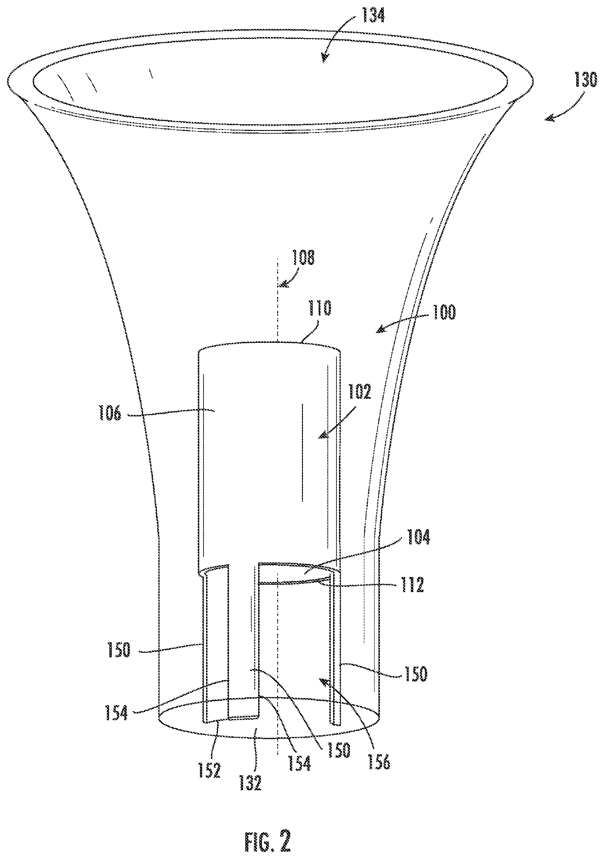
[0042]According to various other implementations, a plant holding system includes a vase defining an inner cavity with a bottom surface. The plant holding system also includes a plant holder, such as the plant holder described above. The plant holder is disposed within the inner cavity of the vase, and distal ends of the legs are dispose...


PUM


Abstract

Various implementations include a plant holder that includes at least one wall having an inner surface, a first end, and a second end. The inner surface of the at least one wall defines a channel, along with a first opening to the channel and a second opening to the channel. The first end and the second end of the at least one wall are spaced apart along a central axis that extends through the openings. The plant holder also includes at least two legs extending axially from and being spaced around a perimeter of the second end of the at least one wall. Adjacent edges of adjacent legs define a gap therebetween.

Description

BACKGROUND[0001]When plants are placed in a traditional vase, the ends of the stems of the plants must be trimmed and the water must be changed periodically to maintain the plants' health over time. Traditional vases for holding plants do not allow easy access to stems and require the originally designed plant bouquet to be removed and disturbed to change the water and cut the stems. In applications in which large numbers of plant arrangements are maintained (e.g., within the hospitality and floral industries), trimming stems and changing water in traditional vases can be time consuming. Thus, a need exists for a device that allows plant bouquets to be easily removed from a vase without disturbing the arrangement and allows for easy access to the plant stems for trimming.BRIEF SUMMARY[0002]Various implementations include a plant holder. The plant holder includes at least one wall and at least two legs. The wall has an inner surface, a first end, and a second end. The inner surface o...

Claims


Application Information

Patent Timeline
IPC IPC(8): A01G9/02
CPCA01G9/02A47G7/07A47G7/06
Inventor WHITE, JAMES EDWARD
Owner UNIVERSITY OF ALABAMA
Why Eureka
Try Eureka