Ball joint

a ball joint and ball bearing technology, applied in the field of ball bearing joints, can solve the problems of reducing the load-bearing ability increasing the weight of the motor vehicle, and undesired expansion of the ball bearing joint, so as to increase the axial load-bearing ability

Inactive Publication Date: 2019-12-26
ZF FRIEDRICHSHAFEN AG
View PDF15 Cites 5 Cited by
  • Summary
  • Abstract
  • Description
  • Claims
  • Application Information

AI Technical Summary

Benefits of technology

[0005]Starting from there the purpose of the present invention is to be able to increase the axial load-bearing ability of a ball joint of the type mentioned at the start, without making the joint significantly larger.
[0008]This makes it possible to obtain the desired deflection ability of the ball journal relative to the housing in the longitudinal direction, whereas in contrast in the transverse direction the axial overlap and hence the axial load-bearing ability of the ball joint are increased. This is possible because in many practical applications the deflection of the ball journal relative to the housing is a maximum only in one direction, but is much smaller in other directions. Thus, it is not necessary to have a circular locking ring.
[0009]The increased axial overlap in the transverse direction leads in particular to an additional area segment which is available for axial support, so that the surface pressure in the axial direction can be reduced. Advantageously, this also results in less wear. The additional area segment is also, in particular, advantageous for measuring the spring rigidity in accordance with wear tests and can if necessary also be regarded as an additional adjustment element. Although it is true that due to the non-circular locking ring opening the ball joint as a rule has to be fitted in a particular orientation and / or direction, this is acceptable considering the space, weight and cost advantages. In particular, the directional fitting should present no problem in the case of an integrated support joint, even when the fitting is carried out purely by friction.
[0015]According to an embodiment the end face of the locking ring facing away from the joint ball lies in an end-face plane transverse to the central axis, which for example is also called the outer end plane. This has the advantage that conventional techniques for dosing the ball joint can be used, such as rolling.

Problems solved by technology

Thus, the overlap reduction reduces the load-bearing ability of the ball joint in the axial direction.
However, a larger joint is undesired since the fitting space in motor vehicles is restricted.
Moreover, a larger joint increases the weight of the motor vehicle and hence its fuel consumption.
Finally, due to the increased use of material alone, making the joint larger increases the manufacturing costs of the joint.

Method used


Image

  • Ball joint
  • Ball joint

Examples


Embodiment Construction

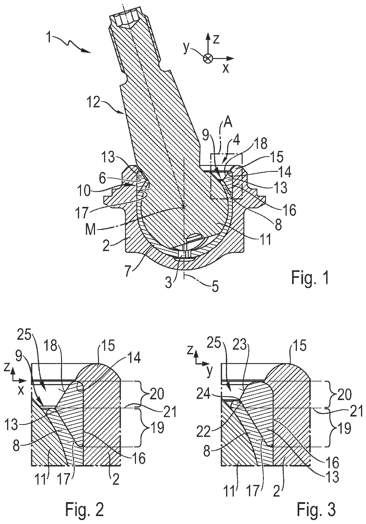
[0038]FIG. 1 shows a sectioned view of an embodiment of a ball joint 1, which comprises a housing 2 with an inside space 3 and a housing opening 4, such that in an area facing toward the housing opening 4, the inside space 3 is delimited by a cylindrical inner circumferential surface 6 of the housing 2 that extends around a central axis 5. The central axis 5 extends in an axial direction z. In addition a longitudinal direction x and a transverse direction y are shown, such that the longitudinal direction x extends transversely to the axial direction z and the transverse direction y extends transversely to the axial direction z and to the longitudinal direction x. In FIG. 1 the transverse direction y extends into the plane of the drawing.

[0039]In the inside space 3 is arranged a ball socket 7 open toward the housing opening 4, which has an overlap area 8 on its side facing toward the housing opening 4, this overlap area delimiting a ball socket opening 9 of the ball socket 7. Further...


PUM


Abstract

A ball joint with a housing having a housing opening with which a central axis (5) extending in an axial direction (z) and emerging through the housing opening is associated. A ball journal (12) having a joint ball (11) which, with its joint ball (11), is fitted and able to move within the housing and which extends out of the housing through the housing opening. A locking ring (13) is securely fitted into the housing which surrounds the central axis (5) and supports the joint ball (11) in the axial direction (z). The ring delimits a locking ring opening (25) through which the ball journal (12) extends, such that the locking ring opening (25) is larger, in a longitudinal direction (x), that extends transversely to the central axis (5) than in a transverse direction (y), that extends transversely to the central axis (5) and to the longitudinal direction (x).

Description

[0001]This application is a National Stage completion of PCT / EP2018 / 053243 filed Feb. 9, 2018, which claims priority from German patent application serial no. 10 2017 203 711.3 mailed Mar. 7, 2017.FIELD OF THE INVENTION[0002]The invention relates to a ball joint, with a housing that has a housing opening with which a central axis extending in an axial direction and passing through the housing opening is associated, a ball journal having a joint ball, which is fitted with its joint ball able to move in the housing, and which extends out of the housing through the housing opening, and a locking ring fixed securely in the housing, which ring surrounds the central axis and supports the joint ball in the axial direction, the ring delimiting a locking ring opening through which the ball journal extends.BACKGROUND OF THE INVENTION[0003]Such a ball joint is used for example in the chassis of a motor vehicle, and is known for example from DE 10 2015 211 005 A1.[0004]For the support of the jo...

Claims


Application Information

Patent Timeline
Patent Type & Authority Applications(United States)
IPC IPC(8): F16C11/06
CPCF16C2326/05F16C11/0638F16C2229/00F16C11/0628F16C11/069
Inventor GRÄBER, JÜRGEN
Owner ZF FRIEDRICHSHAFEN AG
Why Eureka
Try Eureka