Multiple-firing suture fixation device and methods for using and manufacturing same

a technology of multi-firing sutures and fixing devices, which is applied in the field of multi-firing sutures fixing devices and methods for using and manufacturing same, and can solve problems such as knot unraveling, knots could come loose, and forces working against keeping the firs

Active Publication Date: 2020-01-09
EDWARDS LIFESCIENCES AG
View PDF0 Cites 0 Cited by
  • Summary
  • Abstract
  • Description
  • Claims
  • Application Information

AI Technical Summary

Benefits of technology

[0011]The multiple-firing securing device does not generate waste during a procedure and allows enough securing structures (e.g., disks, crimps) for a complete procedure to be loaded before the procedure and, therefore, do not need to be individually loaded during the procedure. The multiple-firing securing device holds a number of securing structures within the device prior to performing a procedure. During the procedure, the multiple-firing securing device automatically loads a single securing structure in a delivery position that is ready to be secured and is in a position allowing cords to pass therethrough for securing after the cords are tightened. The multiple-firing securing device provides a mechanism that passes the cords through one securing structure, placing the securing structure in a ready-to-fire position. The multiple-firing securing device provides a reliable, reusable way of passing the cords through one securing structure at a time for each of the multiple loaded securing structures. There is no waste or separate parts to account for during or after a surgical procedure.
[0013]Traditionally, surgical sutures are cut by advancing a movable knife One exemplary embodiment of the multiple-firing securing device uses a movable knife. Another exemplary embodiment of the multiple-firing securing device uses a fixed knife and a blunt pusher that contacts the suture and moves it to and against the fixed knife for cutting. This configuration prevents cutting from happening prematurely and allows precise control of the distance that the suture is cut from the securing device. A further exemplary embodiment of a multiple-firing securing device uses a movable inner cylinder movably housed within an outer cylinder having a window through which the cord is passed, the adjoining edges of the window and an edge of the inner cylinder forming scissors that cut the cord when the inner cylinder is moved distally past a given extent. This configuration prevents cutting from happening prematurely and allows precise control of the distance that the suture is cut from the disk.
[0018]In the exemplary embodiments, the shuttle contains various interlocks. One interlock prevents the formed wire snare from being presented until the shuttle is in a distal-most position. Another interlock prevents the shuttle from moving proximally if the snare is extended in any way. Another interlock holds the shuttle at a distal-most position for (1) extending the snare and (2) retracting the cords with movement of a shuttle saddle to position the cords in a radiused tip of the snare. Another interlock prevents the snare from moving when the cords reside in the tip and the shuttle is moving proximally to pass the cords through the crimp and thereafter present the cords outside the shaft for handling by the user.
[0020]Ideally, when the handle is in the middle of any of the crimping, cutting, or loading processes, the handle prevents the shuttle from moving away from the nose of the handle. In contrast, when the shuttle is advanced away from the handle, handle functions may be enabled or disabled as appropriate when the shuttle is either moving or is away from the nose.
[0031]An exemplary embodiment of the cord-securing devices and methods described herein includes a sensor associated with the device to detect and measure the amount of tying force that is being imparted by the user to the cords when tying a first knot at a location. This sensor supplies information to a display (e.g., on the handle) that shows either the amount of tying force or whether or not the amount of tying force is equal to or greater to a pre-set limit, or both. The display can take any form, such as an LCD display with graphics, an LED with yellow, green, and red display colors, or just a simple yes / no mechanical and / or electrical indicator that sufficient tying force is being applied. In this way, the user can maintain pressure against the first knot until the second knot secures the first knot. There is, accordingly, no time for loosening the first knot before the second knot secures the first knot in place with the tying force intact and leaving the first knot at the locking state. A surgeon can determine, with actual measurements or with pre-supplied data, the desired tying force for a particular cord to be tied (e.g., a surgical suture) and, during tying, to know dynamically if the cord is being tied and kept at the tying force after the cord is released.

Problems solved by technology

If left alone, the knot could come loose.
However, there are various counter-forces working against keeping the first knot within the locking state.
As such, once the surgeon places the first knot in the locking state and releases the first knot to tie the second locking knot, there is a great chance that that first knot will unravel and leave the locking state, thereby reducing the force from the desired tying force.
After much experience with tying surgical knots, a surgeon can tie them with approximately the same tying force, but this approximation is neither consistent nor accurate.
For each surgical procedure, it is possible to accurately measure the desired tying force, but there is no way for a surgeon to know with any confidence that his / her hand-tied knot is tied close to or at the desired tying force.
Drawbacks of such surgical instruments include being limited to use with a single suture and a single crimp and generate significant waste during the suture tying process, which waste must be accounted for because there exists the possibility that the waste could be lost within the patient during surgery if safeguards are not taken.
Care must be taken because there is no positive method of securing the crimp into the ready position within the crimping device.
If the crimp becomes dislodged, it may not form a proper securing crimp.
This may require the suture to be replaced, which may be extremely difficult.
If during the process of passing the sutures through the crimp the sutures do not fully pass through the crimp, it is possible that the very small crimp could be dislodged from the crimping device and potentially lost within the patient.
As with the surgeon's hands, there is no way for such prior art instruments to know whether the first knot is tied with a force that is close to or at the desired tying force and, especially, is not so much greater to cause harm at the surgical site.

Method used


Image

  • Multiple-firing suture fixation device and methods for using and manufacturing same
  • Multiple-firing suture fixation device and methods for using and manufacturing same
  • Multiple-firing suture fixation device and methods for using and manufacturing same

Examples


Embodiment Construction

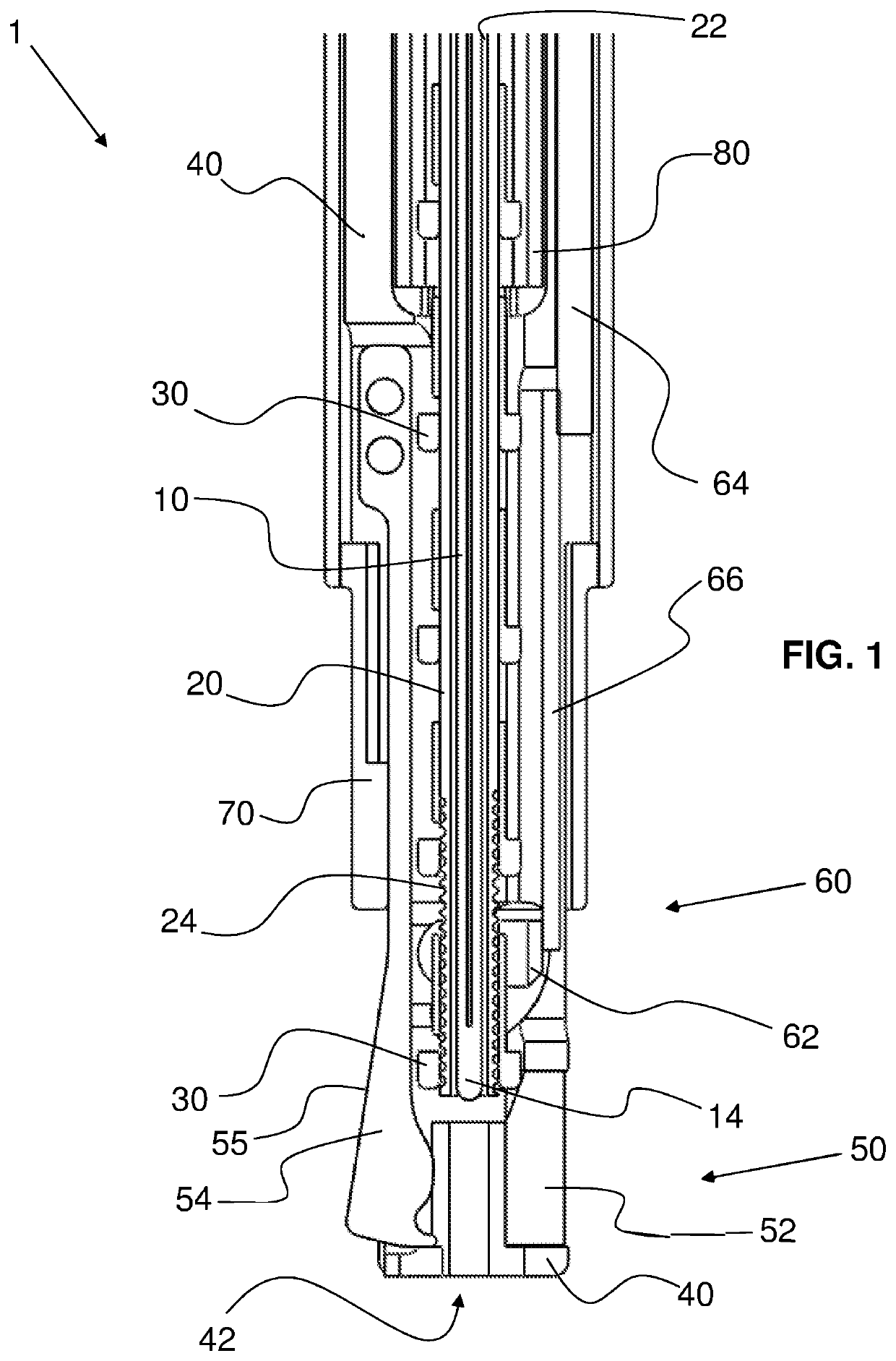
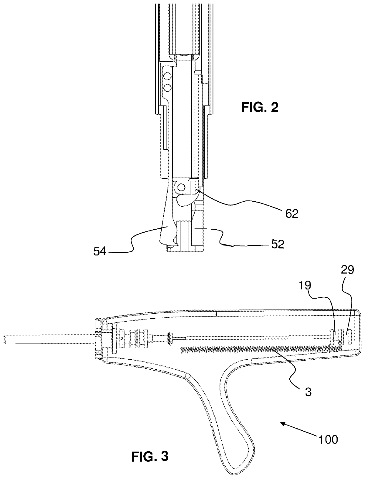
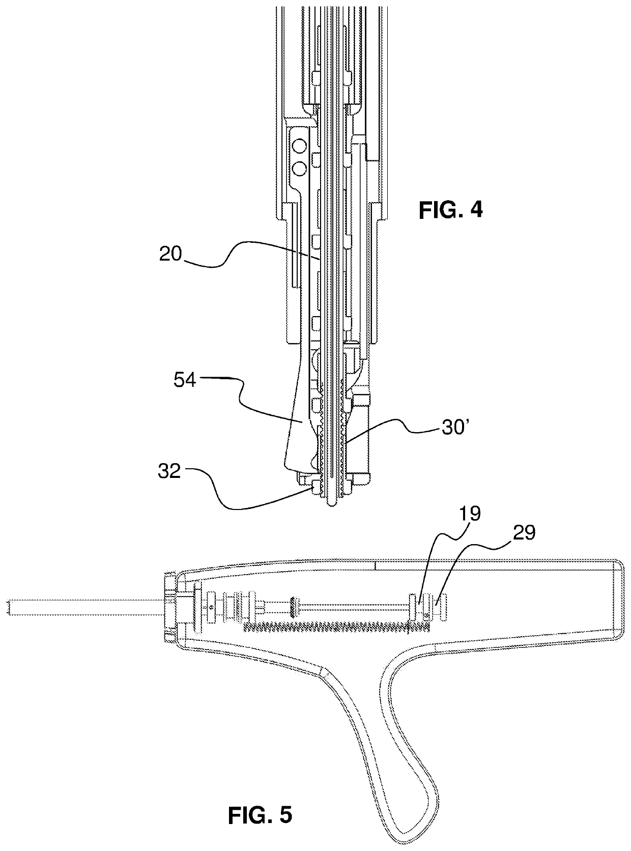
[0227]As required, detailed embodiments of the systems and methods are disclosed herein; however, it is to be understood that the disclosed embodiments are merely exemplary of the systems and methods, which can be embodied in various forms. Therefore, specific structural and functional details disclosed herein are not to be interpreted as limiting, but merely as a basis for the claims and as a representative basis for teaching one skilled in the art to variously employ the systems and methods in virtually any appropriately detailed structure. Further, the terms and phrases used herein are not intended to be limiting; but rather, to provide an understandable description of the systems and methods. While the specification concludes with claims defining the features of the systems and methods that are regarded as novel, it is believed that the systems and methods will be better understood from a consideration of the following description in conjunction with the drawing figures, in whic...


PUM


Abstract

A multiple-firing clip device includes a hollow shaft defining a lateral opening communicating with an environment and a distal shaft portion between the lateral opening and a distal end opening. A shuttle longitudinally moves on the shaft and comprises a shuttle body defining a lumen surrounding the shaft, a snare, and a snare-extender slide defining a snare track to form a snare travel path in which the snare is disposed from the body and through the track and a portion of the body. The slide moves along a given extent defining a slide distance and a distal end and movement of the slide to the distal end shortens the snare travel path to extend the snare portion through the lateral opening, through the distal shaft portion, and distally out from a distal side of the body longer than the given extent to secure a suture with the snare.

Description

CROSS-REFERENCE TO RELATED APPLICATIONS[0001]This application is a continuation of U.S. patent application Ser. No. 14 / 965,323, filed Dec. 10, 2015, which claims the benefit of U.S. Patent Application No. 62 / 090,097, filed Dec. 10, 2014; U.S. Patent Application No. 62 / 103,045, filed Jan. 13, 2015; U.S. Patent Application No. 62 / 164,016, filed May 20, 2015; and U.S. Patent Application No. 62 / 096,749, filed Dec. 24, 2014, the entire disclosures which are incorporated by reference. This application is also related to: U.S. patent application Ser. No. 13 / 715,640, filed Dec. 14, 2012, now U.S. Pat. No. 9,017,347; U.S. patent application Ser. No. 13 / 938,071, filed Jul. 9, 2013; U.S. patent application Ser. No. 14 / 307,694, filed Jun. 18, 2014; U.S. patent application Ser. No. 14 / 329,797, filed Jul. 11, 2014; U.S. patent application Ser. No. 14 / 543,240, filed Nov. 17, 2014; U.S. patent application Ser. No. 14 / 658,575, filed Mar. 16, 2015; and U.S. patent application Ser. No. 14 / 868,741, fil...

Claims


Application Information

Patent Timeline
Patent Type & Authority Applications(United States)
IPC IPC(8): A61B17/04
CPCA61B2017/0488A61B17/0487A61B17/0485A61B2017/00358A61B17/0467A61B2017/00017A61B2017/00119A61B2017/00349A61B2017/00398A61B2017/00477A61B2017/00734A61B2017/00876A61B2017/00902A61B2017/0496A61B2090/064A61B2090/309A61B2090/0807A61B2090/3937
Inventor DEVILLE, DEREK DEESMITH, KEVIN W.KIRK, MICHAEL WALTERRIVERA, CARLOSNUNEZ, GEORGEBALES, JR., THOMAS O.KLINE, KOREYPALMER, MATTHEW A.MCBRAYER, M. SEANCARTLEDGE, RICHARD GEORGEMENDEZ, MAX PIERREDANG, KEVIN K.JANISH, BRYAN A.MIRAKI, MANOUCHEHR A.
Owner EDWARDS LIFESCIENCES AG
Why Eureka
Try Eureka