Automated drilling-fluid additive system and method

a technology of additive system and additive system, which is applied in the directions of transportation and packaging, mixing, and drilling well accessories, etc., can solve the problems of high undesirable, large amount of agitation or turbulence in the process of blending thick drilling mud, and easy problems in storage and settling tanks, so as to eliminate turbulence

Active Publication Date: 2021-11-30
COLLINS KYLE
View PDF15 Cites 2 Cited by
  • Summary
  • Abstract
  • Description
  • Claims
  • Application Information

AI Technical Summary

Benefits of technology

[0014]This invention provides an automated drilling-fluid additive system and method for on-site real-time analysis and additive treatment of drilling fluid to be directly injected into a well without additional storage or handling. Under the real-time control of the controller, drilling fluid flowing through a conveyer pipe is analyzed in the inline diagnostic unit and appropriate additives stored in totes are added in a lower-pressure expanding additive area. The drilling fluid is thoroughly blended in a blending area having turbulence vanes and then passed through a collimator area in order to eliminate turbulence and create a laminar flow of blended drilling fluid which is suitable for direct delivery to a high-pressure pump for injection into the well. The system is contained in a secure transportable container structure for on-site use. An operator either on-site or at a remote distance can monitor and direct the operation of the automated drilling-fluid additive system through a remote communication unit.

Problems solved by technology

The process of blending the thick drilling mud requires a large amount of agitation or turbulence.
Even where additives have been blended in using a semi-automated process, the blended drilling mud must be held in and drawn from an intermediate storage and settling tank in order to eliminate the turbulence necessarily introduced in blending the additives with the drilling mud, but which is highly undesirable for feeding into the high-pressure injection pump.
The storage and settling tank is prone to problems such as overflowing, emptying, or allowing additives to settle out.

Method used


Image

  • Automated drilling-fluid additive system and method

Examples


Embodiment Construction

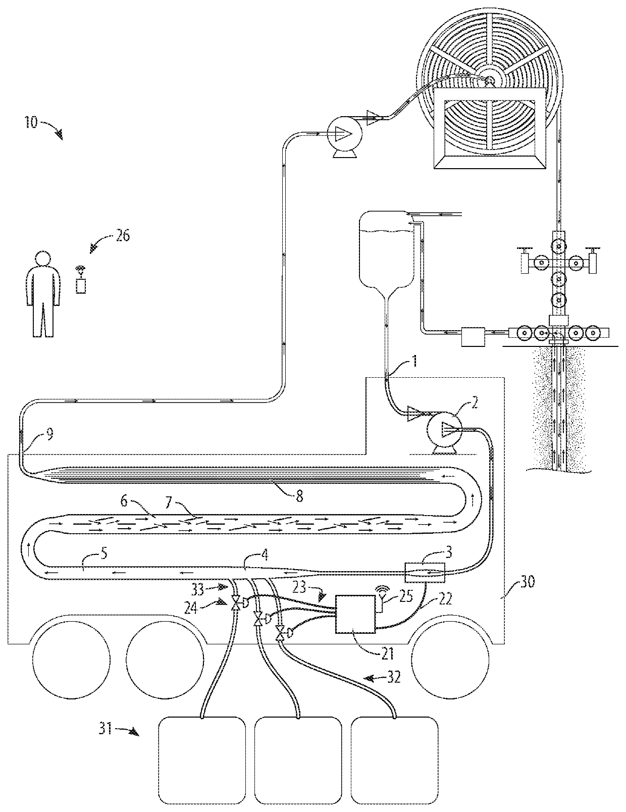
[0017]Referring to FIG. 1, the automated drilling-fluid additive system and method 10 is shown schematically, in use in coiled-tubing drilling operations with varying mixtures of fresh and returned drilling fluid supplied and with a smooth laminar flow drilling fluid blended with desired additives provided directly to a high-pressure injection pump for injection into the well.

[0018]The automated drilling-fluid additive system and method 10 provides a container structure 30 which provides for transportation, security, and safety in use at a drilling site and movement from site to site. A wheeled trailer-type structure, as shown, or a wheel-less shipping container type structure are appropriate.

[0019]Standard totes 31, each containing an additive, are placed on or near the container structure 30 and are connected to the structure by tote fluid lines 32. Each tote can be connected or disconnected for the purpose of replacing an empty tote or connecting totes with a different additive a...


PUM

PropertyMeasurementUnit
temperatureaaaaaaaaaa
pressureaaaaaaaaaa
pressure dropaaaaaaaaaa

Abstract

An automated drilling-fluid additive system and method for on-site real-time analysis and additive treatment of drilling fluid to be directly injected into a well without additional storage or handling. The drilling fluid includes returned drilling fluid intended to be re-used, which has a variety of viscosity and other qualities resulting from its various preceding use. The target drilling fluid will have a variety of viscosity and other qualities depending upon and changing with various phases of drilling operations and various conditions encountered. The drilling fluid is analyzed in real time as it flows into the automated drilling-fluid additive system, and various additives are added to and thoroughly blended with the drilling fluid as needed to achieve the desired result. The blended drilling fluid is collimated to produce a laminar flow and is discharged from the automated drilling-fluid additive system in the proper condition for direct injection into a well without any storage in a holding tank and without any further processing, treatment, or handling.

Description

BACKGROUND OF THE INVENTION[0001]This invention provides an automated drilling-fluid additive system and method.[0002]Drilling fluid or drilling mud is used in drilling operations and is used extensively and for a variety of uses in coiled-tubing, directional drilling, and fracking operations. The drilling mud is injected into the well and usually returns to the surface though the annulus. The returned drilling mud contains shavings and other debris, and often returns with changed viscosity and other qualities, and serves as an indicator of the conditions at the work string and along the drill string.[0003]It is often desired to re-use the returned drilling mud after removal of debris and after reconstituting and reconditioning the returned drilling mud with additives to restore the desired viscosity and other qualities. Even when using fresh drilling mud, it is often desired to adjust the qualities with additives appropriate to the particular conditions and the particular operation...

Claims


Application Information

Patent Timeline
Patent Type & Authority Patents(United States)
IPC IPC(8): E21B21/06E21B21/10E21B44/00B01F3/12E21B49/08E21B43/26
CPCE21B21/062B01F3/1214E21B21/106E21B44/00E21B49/084E21B43/26E21B21/06B01F25/311B01F25/314B01F25/4337B01F33/5023B01F35/2136B01F35/2203B01F23/511
Inventor COLLINS, KYLE
Owner COLLINS KYLE
Why Eureka
Try Eureka