Fan-shaped material distributor

A distributing device and fan-shaped technology, applied in chemical instruments and methods, magnetic separation, solid separation, etc., can solve the problems of magnetic separator processing volume fluctuation, process control influence, and service cycle decline, so as to improve the equalization effect and detect Accurate results and prolonged service life

Active Publication Date: 2016-03-09
江苏紫润建设有限公司
View PDF9 Cites 8 Cited by
  • Summary
  • Abstract
  • Description
  • Claims
  • Application Information

AI Technical Summary

Problems solved by technology

With the enlargement of the drum magnetic separator, the longest width of the magnetic drum has reached 3 meters, or even 4.5 meters. During the magnetic separation production process, it was found that this one-point ore distribution form has uneven separation of ore pulp, resulting in The horizontal component of the magnetic separator is uneven, resulting in the phenomenon of more in the middle and less on both sides, thereby reducing the separation effect of the magnetic separator. When the pulp flows out of the ore feeding pipeline, the speed is very high. Under the friction of grains, the service life of the side of the distribution box and the bottom box of the magnetic separator will be greatly reduced, and the increase in equipment operating costs will bring huge economic losses to the enterprise.
[0005] In addition, due to the limitations of the magnetic force of the magnetic separator, the rotating speed of the cylinder, the particle size of the mineral and the daily processing capacity, the concentration of the ore pulp from the upstream has a great influence on the process control of the magnetic separator.
For example, at the same feed rate, the mineral content of pulp with different concentrations is not the same, which makes the processing capacity of the magnetic separator fluctuate greatly. On the one hand, there may be insufficient utilization of the processing capacity, on the other hand, there may be excessive Load processing, resulting in waste of useful minerals

Method used


Image

  • Fan-shaped material distributor
  • Fan-shaped material distributor
  • Fan-shaped material distributor

Examples


Embodiment 1

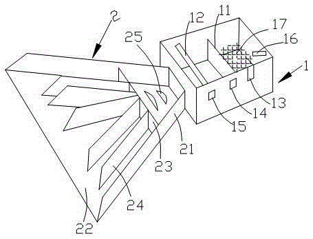
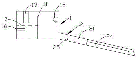
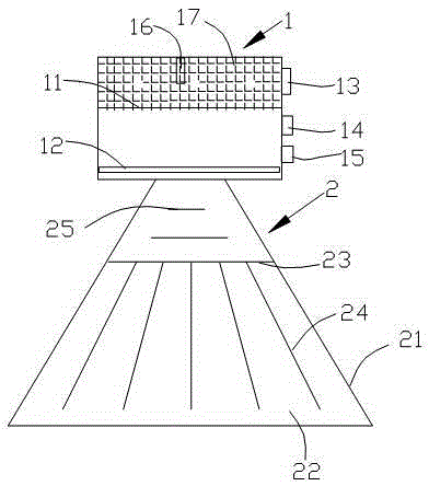
[0032] Such as Figure 1~3 The fan-shaped distributor shown includes a box body 1 and a distribution tank 2; the box body 1 is divided into a slurry inlet tank and a slurry outlet tank by an overflow plate 11. A valve 13 and an online pulp concentration meter 16 are arranged on the inner wall of the slurry inlet tank; a dilution water pipe 12 is arranged on the upper part of the slurry outlet tank parallel to the slurry outlet; a controller 14 and a controller 14 are arranged on the outer wall of the tank. A pump 15 that supplies water to the dilution water pipe 12; a controller 14 is connected to an online slurry concentration meter 16, a valve 13, and a pump 15;

[0033] The distribution trough 2 is fan-shaped and includes side plates 21 , bottom plates 22 , one baffle plate 23 , six deflector plates 24 , and two buffer plates 25 . The baffle plate 23 is parallel to the pulp outlet and connected with the bottom plate 22 and the side plate 21 . The deflector 24 is connected...


PUM


Abstract

The invention relates to the technical field of mineral separation equipment and discloses a fan-shaped material distributor. The fan-shaped material distributor comprises a box body and a material distribution chute, wherein the box body is divided into pulp inlet trough and a pulp outlet trough by an overflow plate; a valve and a plurality of on-line ore pulp concentration meters are arranged on the inner wall of the pulp inlet trough; a diluting water pipe is arranged at the upper part, parallel to a pulp outlet, of the pulp outlet trough; a controller and a pump for supplying water to the diluting water pipe are arranged on the outer wall of the box body; the controller is connected with the on-line ore pulp concentration meters, the valve and the pump respectively; the material distribution chute is shaped like a fan and comprises side plates, a bottom plate, a baffle plate, flow guiding plates and a plurality of buffer plates; and a flow stabilizing grate is arranged in the pulp inlet trough. The controller of the fan-shaped material distributor can carry out adjustment through the valve and the pump according to the treatment capacity of a downstream magnetic separator to obtain appropriate ore pulp. The ore pulp is mixed and guided by the material distribution chute to uniformly flow to a bottom box along a cylinder of the magnetic separator.

Description

technical field [0001] The present invention relates to the technical field of mineral processing equipment, and more specifically, to a fan-shaped distributor. Background technique [0002] The wet drum magnetic separator is mainly composed of three main parts: cylinder, magnetic system and bottom box. The cylinder is set above the bottom box. It is made of non-magnetic material-stainless steel plate rolled and welded. It is driven by a motor to rotate; the magnetic poles of the magnetic system are arranged alternately along the direction of rotation of the cylinder, and they are fixed during operation. Its working principle is: after the ore slurry is fed into the bottom box by the fan-shaped distributor, under the action of the ore feeding water flow, the ore particles enter the mine feeding area at the bottom of the box in a loose state. Under the action of the magnetic field, the magnetic mineral particles are attracted to the surface of the cylinder against gravity an...

Claims


Application Information

Patent Timeline
Patent Type & Authority Applications(China)
IPC IPC(8): B03C1/005
CPCB03C1/005
Inventor 吴振宇
Owner 江苏紫润建设有限公司
Why Eureka
Try Eureka