Mixed combustion visual combustor

A mixed combustion and burner technology, which is applied in combustion chambers, combustion methods, and combustion equipment, can solve problems such as unfavorable combustion diagnosis, disrupted ignition sequence, and difficult-to-ignite fuel grains, so as to avoid serious backflow of gas outlet and reduce Disturbance of combustion environment, effect of good flame stability

Active Publication Date: 2021-02-02
NORTHWESTERN POLYTECHNICAL UNIV
View PDF5 Cites 8 Cited by
  • Summary
  • Abstract
  • Description
  • Claims
  • Application Information

AI Technical Summary

Problems solved by technology

[0006] 1. Since the cross-sectional diameter of the outlet of the oxidant injector is smaller than the cross-sectional size of the square channel in the combustion chamber, the gas flow will produce a sudden expansion effect, resulting in a backflow zone, and the tail end of the solid fuel will cause the flow to produce a back step effect, so it is easy to appear in the combustion flow field Multiple vortex structures interfere with the integrity of the flow field structure and are not conducive to combustion diagnosis
[0007] 2. The ignition method adopts the ignition charge, which makes it difficult to ignite the fuel grain instantaneously and comprehensively, and a large amount of soot is easily generated at the instant of ignition, thereby covering up the effective characteristic information of the flow field ...

Method used


Image

  • Mixed combustion visual combustor
  • Mixed combustion visual combustor
  • Mixed combustion visual combustor

Examples


Embodiment 1

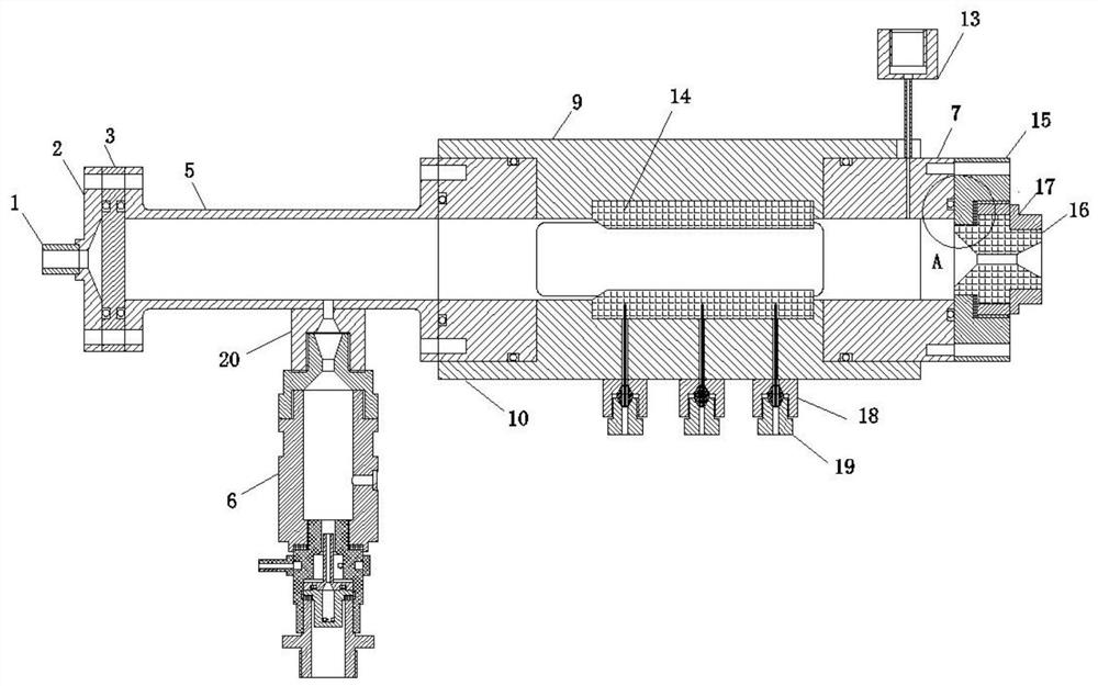
[0082] Embodiment 1: The fuel is cut into several long strips with an end surface size of 20mm×20mm and a length of 150mm, and the grains are finely trimmed to have a forward angle of 30°. Weigh absolute ethanol and polyvinyl butyral according to the mass fraction of 92% and 8% to configure the coating solution, slowly add polyvinyl butyral to absolute ethanol, place it in a water bath at 50°C, and use a glass rod to Stir continuously until the polyvinyl butyral is completely dissolved, and use the prepared coating solution to evenly coat the side of the solid fuel 14 to ensure that the charges burn in parallel layers. Use a twist drill bit with a diameter of 0.5mm in one of the solid fuel 14 rods, the depth of the fuel inner hole is 2 / 3 of the height of the fuel, and the drilling position is coaxial with the through hole at the bottom of the lower top cover 10 of the combustion chamber. Weigh epoxy resin (A glue) and curing agent (B glue) according to the mass ratio of 5:3, s...


PUM


Abstract

The invention discloses a mixed combustion visual combustor, and belongs to the technical field of rocket engines. The combustor comprises an air inlet assembly, a rectification section, a combustionchamber and a coaxial ignition torch; the rectification section is coaxially installed between the air inlet assembly and the combustion chamber; the coaxial ignition torch is installed on the outer circumferential face of the rectification section in the radial direction of the rectification section; the rectifying section is of a columnar structure with a rectangular through hole in the axial direction; a round flange plate and a square flange plate are arranged at the two ends of the rectifying section respectively; the rectifying section is coaxially and hermetically connected with the airinlet assembly through the round flange plate and coaxially and hermetically connected with the combustor inlet end through the square flange plate; a circular hole is formed in the peripheral wall of the rectifying section; the rectifying section is communicated with the coaxial ignition torch through an assembly ignition base; the rectification section is additionally arranged to be matched with the porous injection plate, so that irregular vortex pulsation of airflow is eliminated, and the airflow is stably introduced into the combustion chamber; the section of a flow channel in the rectification section is kept consistent with the section of a flow channel of the combustion chamber, so that a backflow area, namely a vortex structure, is effectively avoided; and therefore a high-quality flow field structure can be obtained in an experiment.

Description

technical field [0001] The invention belongs to the technical field of rocket engines, and in particular relates to a visual mixed combustion burner. Background technique [0002] The solid-liquid hybrid engine has the advantages of high safety and reliability, simple structure, and easy realization of multiple starts and thrust adjustments, and has become an ideal space propulsion power device. However, the low combustion efficiency and combustion surface retreat rate have become the key factors restricting the further development and application of solid-liquid hybrid engines for a long time. Further improvement of the transfer rate is crucial. [0003] Due to the characteristics of separate storage of oxidant and fuel, the combustion in solid-liquid hybrid engines is a typical diffusion combustion with a large diffusion scale. The mixing and combustion process between fuel and oxidant mainly occurs in the thinner combustion boundary layer above the combustion surface. ,...

Claims


Application Information

Patent Timeline
IPC IPC(8): F23R3/28F23R3/42
CPCF23R3/28F23R3/42
Inventor 刘林林陈泽斌胡松启魏祥庚
Owner NORTHWESTERN POLYTECHNICAL UNIV
Why Eureka
Try Eureka