Induction weldable pipe connector having thermally insulated induction weldable socket mouth rims

Active Publication Date: 2020-01-09
HULIOT A C S
View PDF0 Cites 1 Cited by
  • Summary
  • Abstract
  • Description
  • Claims
  • Application Information

AI Technical Summary

Benefits of technology

[0006]In use, application of electromagnetic induction energy to the induction welding mounting melts the solder lining which leads to its expansion. The increased volume of melted solder lining compared to its initial volume of unmelted solder lining leads to pressure buildup inside the induction weldable pipe connector by virtue of the melted solder lining being entrapped by the thermally insulated induction weldable socket mouth rims together with the tubular pipe tang, thereby ensuring improved sealed welding.
[0007]The cover is spaced apart from the induction weldable mounting thereby providing air insulation therebetween for ensuring the cover is only marginally heated by the susceptor sleeve during an electromagnetic induction welding operation. The cover preferably includes an array of ventilation holes for assisting convection cooling of a welded sealed joint.

Problems solved by technology

The ventilation holes meet international UL finger probe standards for preventing inadvertent

Method used


Image

  • Induction weldable pipe connector having thermally insulated induction weldable socket mouth rims
  • Induction weldable pipe connector having thermally insulated induction weldable socket mouth rims
  • Induction weldable pipe connector having thermally insulated induction weldable socket mouth rims

Examples


Example

DETAILED DESCRIPTION OF DRAWINGS

Section 1: Commonly Owned WO 2012 / 137197 A2 Entitled Electromagnetic Induction Welding of Plastic Pipe Distribution Systems

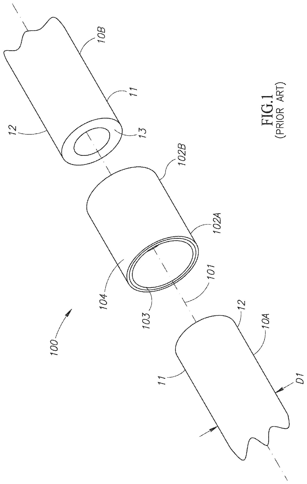
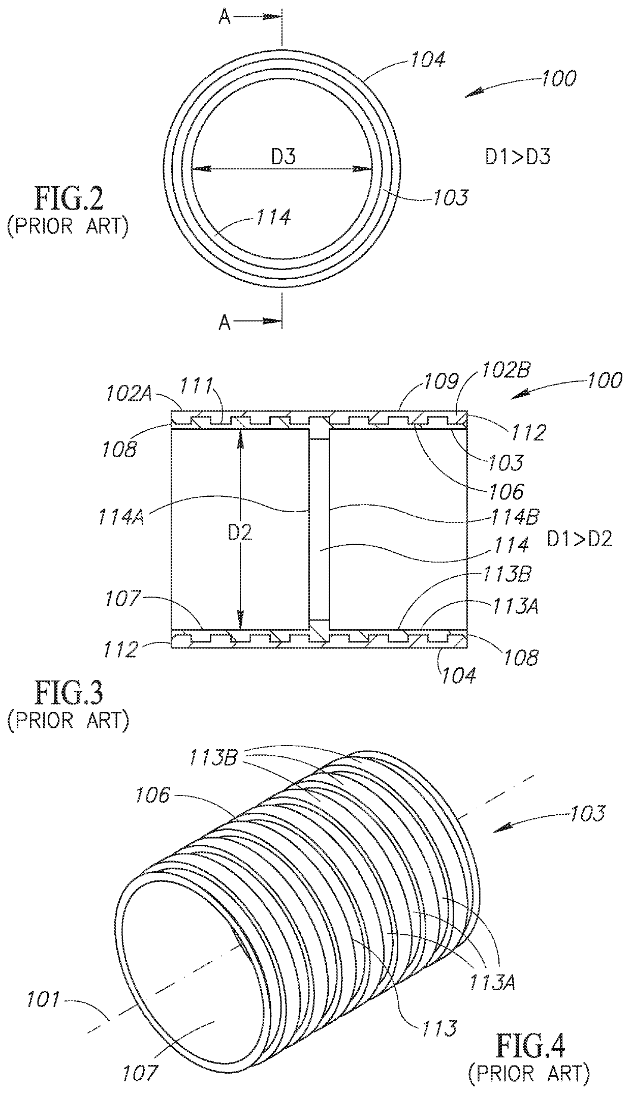
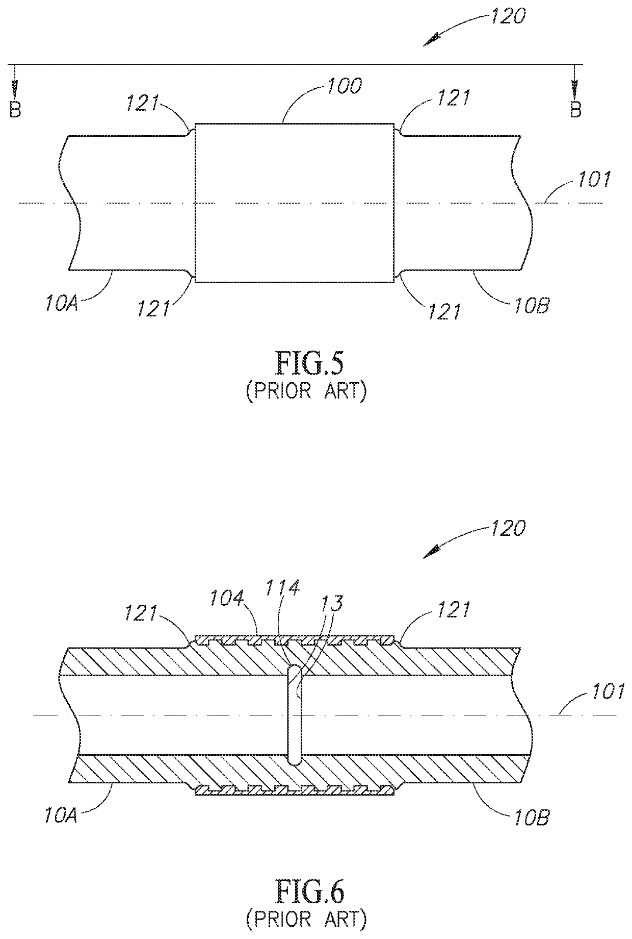
[0046]FIG. 1 to FIG. 4 show an induction weldable pipe connector 100 for electromagnetic induction welding to a pair of same diameter plastic pipes 10. The plastic pipes 10 have an external diameter D1 typically in the range of from 10 mm to 30 mm. The thermoplastic pipes 10 have pipe ends 11. The pipe ends 11 have peripheral external pipe end surfaces 12 and exposed annular pipe end faces 13. The plastic pipes 10 can be fabricated from a single plastic material throughout or alternatively have a multilayer composition.

[0047]The induction weldable pipe connector100 has a longitudinal pipe connector axis 101 and includes two opposite induction weldable pipe sockets 102A and 102B each intended for forced sliding insertion of a pipe end 11 thereinto. The induction weldable pipe connector 100 has a two ply construction including an in...


PUM

PropertyMeasurementUnit
Currentaaaaaaaaaa
Currentaaaaaaaaaa
Currentaaaaaaaaaa

Abstract

Induction Weldable Pipe Connectors (IWPCs) (400) for electromagnetic induction welding with at least one plastic pipe (30). IWPCs (400) include a tubular induction weldable mounting (401) having an opposite pair of induction weldable sockets (404A, 404B), a tubular cover (406) externally mounted on the induction weldable mounting (401), and a tubular pipe tang (407) internally disposed in one induction weldable socket (404A, 404B) for destining an induction weldable socket (404A, 404B) as an induction weldable pipe socket (408A, 408B) for forced sliding insertion of a pipe end (31) thereinto. The cover (406) includes an opposite pair of thermally insulated induction weldable socket mouth rims (426A, 426B) for entrapping melted solder lining (412) inside the induction weldable mounting (401) during an electromagnetic induction welding operation, thereby ensuring improved welding.

Description

FIELD OF THE INVENTION[0001]The invention relates to electromagnetic induction welding of fluid distribution systems in general and Induction Weldable Pipe Connectors (IWPCs) for electromagnetic induction welding of plastic pipes in particular.BACKGROUND OF THE INVENTION[0002]Commonly owned WIPO International Publication No. WO 2012 / 137197 A2 entitled Electromagnetic Induction Welding of Plastic Pipe Fluid Distribution Systems discloses induction weldable pipe connectors and electromagnetic induction coil assemblies for use in clamping the induction weldable pipe connectors on plastic pipes. The plastic pipes can be made from thermoplastics including inter alia PVC, PP, PP-R, HDPE, and the like. And thermosetting plastics including PEX, and the like. The plastic pipes can be fabricated from a single plastic material throughout or alternatively have a multilayer composition to provide a better combination of mechanical and chemical properties. WO 2012 / 137197 induction weldable pipe c...

Claims


Application Information

Patent Timeline
IPC IPC(8): B29C65/36
CPCB29C65/3656B29C65/368B29C66/3242B29C65/561B29K2705/02B29C65/72B29C66/72321B29C66/12441B29C66/12464B29C66/12469B29C66/5221B29C66/52231B29C66/52241B29C66/52292B29C66/52296B29C66/63B29C66/636B29C66/71B29C66/7392B29C66/73921B29C66/7394B29C66/742B29C66/8742B29C66/972F16L47/03B29C66/52298B29C66/52291B29C2795/002B29K2027/06B29K2023/12B29K2023/065B29K2023/0691
Inventor PELEG, RONENYOGEV, ORENFICHTELBERG, YARIV
Owner HULIOT A C S
Why Eureka
Try Eureka