

Probe head with linear probe
a linear probe and probe head technology, applied in the field of probes and probes, can solve the problems of deterioration of the aforesaid, short circuits that may occur to damage the probe card or the device under test, and wear to the body parts, so as to avoid the drop of the probe, avoid the escape of the probe, and avoid the self-rotation of the prob
- Summary
- Abstract
- Description
- Claims
- Application Information
AI Technical Summary
Benefits of technology
Problems solved by technology
Method used
Image

Examples
Embodiment Construction
[0025]First of all, it is to be mentioned that same reference numerals used in the following preferred embodiments and the appendix drawings designate same or similar elements throughout the specification for the purpose of concise illustration of the present invention.
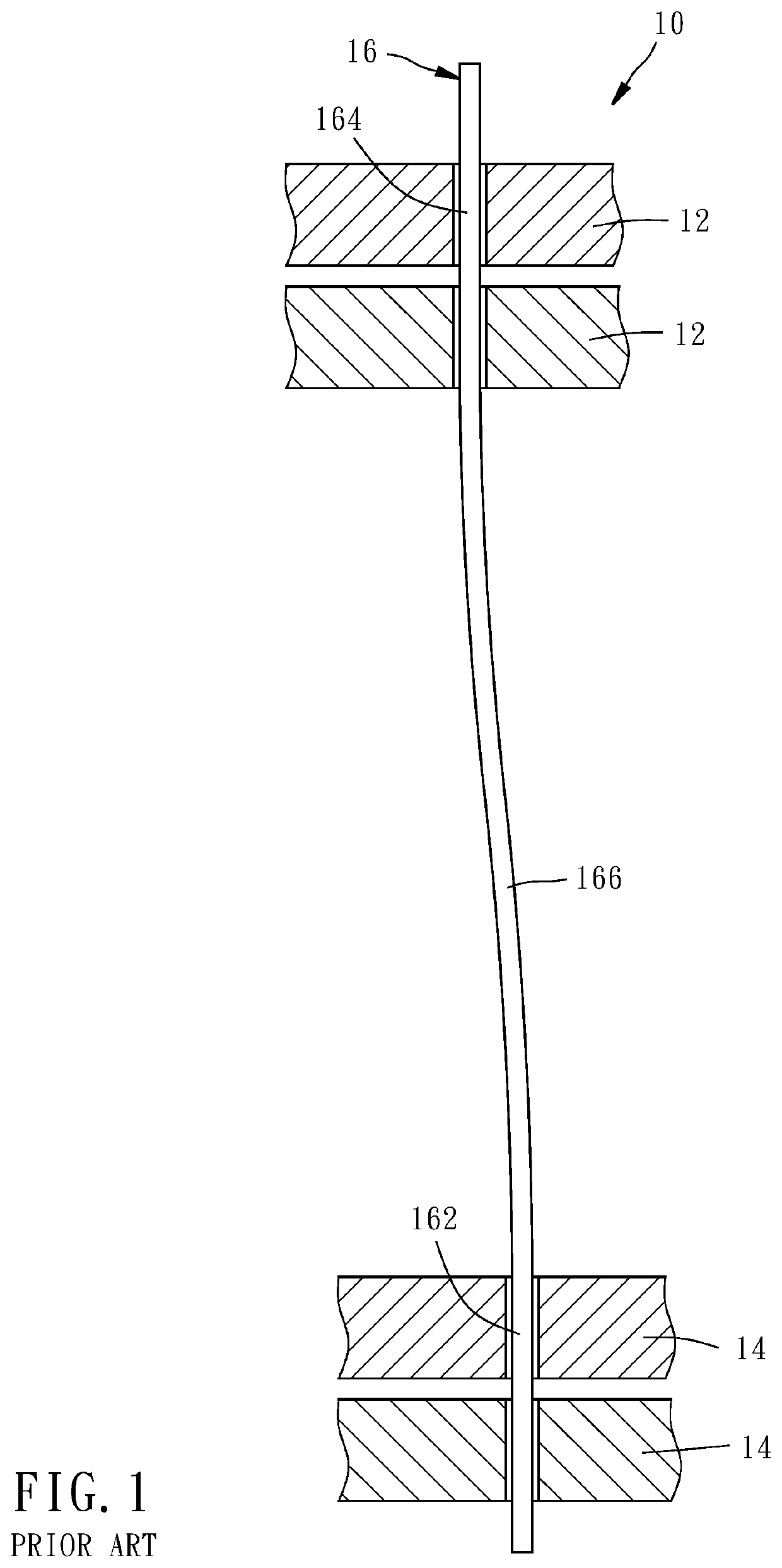
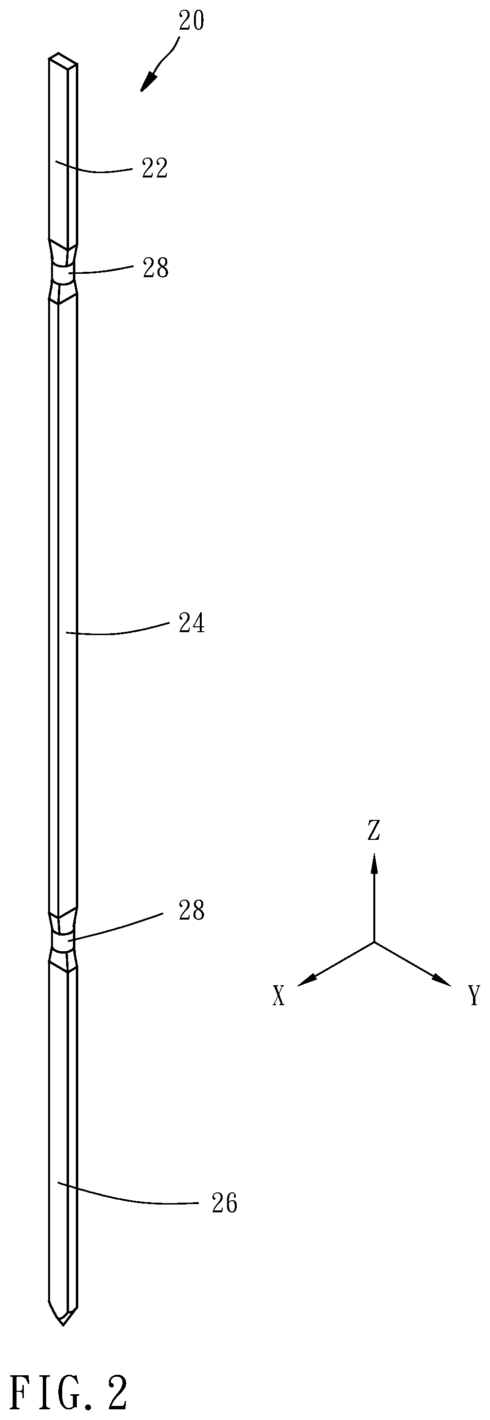
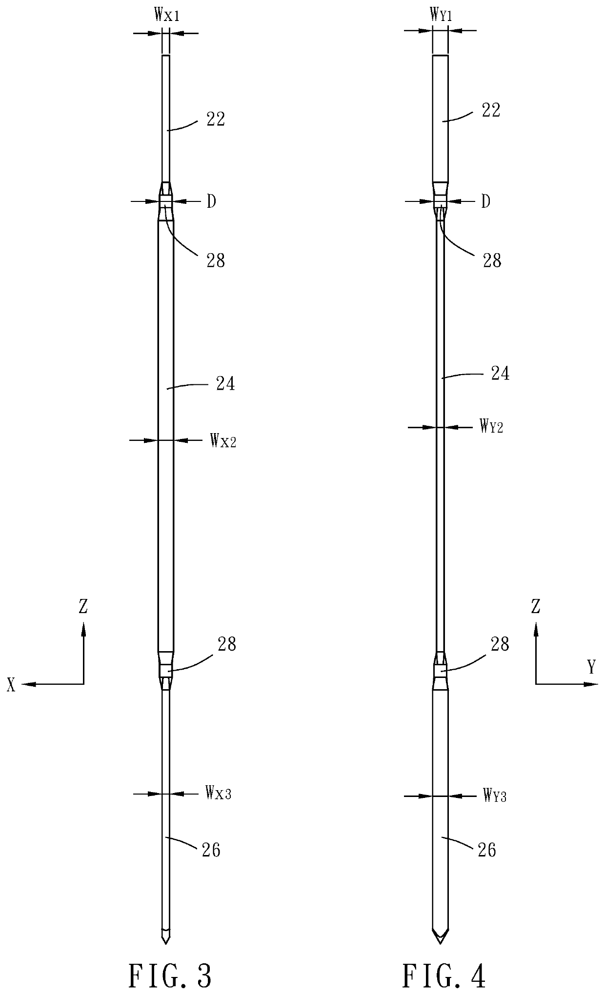
[0026]Referring to FIGS. 2-4, a linear probe 20 according to a first preferred embodiment of the present invention is formed in a way that a cylindrical needle, like the conventional linear probe 16 as shown in FIG. 1, is at least partially flattened to become the linear probe 20. After the manufacturing and before the installation and the use, the linear probe 20 is straight and has a tail portion 22, a body portion 24 and a head portion 26 extending along a longitudinal axis (Z-axis) in order. The technical term “flattened” mentioned in the entire specification and the claims of the present invention refers to that the linear probe is at least partially made into a flat shape in a specific processing manner. For exa...
PUM
 Abstract
Description
Claims
Application Information