Vehicle Wheel Axle Assembly

a technology for axles and vehicles, applied in the direction of axle suspensions, release mechanisms, hubs, etc., can solve the problems of inability to retain the control shaft, inability to service and clean the control shaft, and inability to maintain the control shaft, so as to minimize the frustration, complexity, skill requirements, and eliminate the trial and error

Active Publication Date: 2020-01-16
SCHLANGER RAPHAEL
View PDF0 Cites 0 Cited by
  • Summary
  • Abstract
  • Description
  • Claims
  • Application Information

AI Technical Summary

Benefits of technology

[0024]Still further, this interface may serve to provide tactile feedback to the operator to indicate that the control shaft is in the predetermined axial position relative to the axle sleeve. This provides a helpful convenience for the operator and eliminates the trial-and-error associated with axially positioning the control shaft of conventional through-axle arrangements. In the case where the pre-determined axial position corresponds to the retracted position, this minimizes the operator's frustration, complexity, and skill requirement associated with the wheel installation and removal process.
[0025]Yet further, this engagement interface may be selectively removed by over-extending or hyper-extending the control shaft relative to the axle sleeve to permit access to a retainer. The retainer may be removed or otherwise manipulated such that the control shaft may then be withdrawn and removed from the axle sleeve and from the remainder of the hub assembly. Since the control shaft may be withdrawn and removed from the axle sleeve as described, the operator may swap out different control shafts and may easily service and clean the control shaft without completely disassembling the hub assembly.

Problems solved by technology

This is a great inconvenience to the operator since this is a time-consuming procedure and also requires special tools and skills that many operators may not have.
While there are conventional through-axle axle assemblies available, these assemblies lack any means to retain the control shaft with the axle sleeve and the control shaft may easily become inadvertently separated from the axle sleeve.
This is an inconvenience for the operator.
Further, the control shaft may then become lost or misplaced or damaged.
Further, these conventional through-axle assemblies do not require, nor do they provide, any means to control the axial position of the control shaft relative to the axle sleeve.
Since conventional through-axle assemblies lack this ability for axial position control, the operator must manually position the control shaft in the proper axial position by trial-and-error in order to install and remove the wheel to / from the dropouts of the frame.
For the operator, this adds significant frustration, complexity, and skill requirement to this installation and removal process.

Method used


Image

  • Vehicle Wheel Axle Assembly
  • Vehicle Wheel Axle Assembly
  • Vehicle Wheel Axle Assembly

Examples


Embodiment Construction

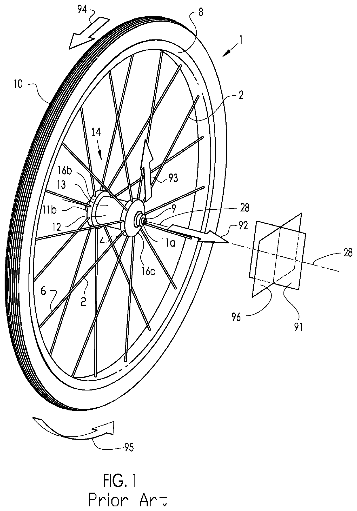
[0055]FIG. 1 describes the basic configuration of an exemplary prior art vehicle wheel, in particular, a bicycle wheel 1, as well as a description of the direction conventions used throughout this disclosure. The hub assembly 14 includes a rotatable hub shell 12 and a stationary axle 9, with bearings (not shown) to facilitate rotation of the hub shell 12 about the axial axis 28. The hub shell 12 includes a hub body 13 with at least two axially spaced hub flanges 16a and 16b, each of which include a means for connecting with the spokes (not shown). The axle 9 includes end faces 11a and 11b to interface with the dropouts (not shown). The axial axis 28 is the axial centerline of rotation of the bicycle wheel 1. The hub flanges 16a and 16b may be contiguous with the hub shell 12 or may be separately formed and assembled to the hub body 13 portion of the hub shell 12. The spokes 2 are affixed to the hub flanges 16a or 16b at their first end 4 and extend to attach the rim 8 at their secon...


PUM


Abstract

A vehicle wheel axle assembly having: an axle sleeve with first and second end faces and an axial opening having a radially inwardly projecting first engagement surface; and a control shaft with a radially outwardly projecting second engagement surface. The control shaft is axially retained to the axle sleeve by an overlie engagement at an engagement interface between the first and second engagement surfaces to limit the axial displacement of the control shaft in a retracting direction relative to the axle sleeve. At least one of: the first engagement surface is in an engagement element discreet from and axially retained to the axle sleeve such that the engagement element may be installed and/or removed to/from the axle sleeve; and the second engagement surface is in an engagement element discreet from and axially retained to the control shaft such that the engagement element may be installed and/or removed to/from the control shaft.

Description

CROSS-REFERENCE TO RELATED APPLICATION[0001]This application claims priority of U.S. Provisional Patent Application 62 / 700,925, filed Jul. 20, 2018.[0002]This application is also a Continuation-In-Part of U.S. patent application Ser. No. 16 / 377,167 filed Apr. 6, 2019, which is currently pending.[0003]U.S. patent application Ser. No. 16 / 377,167 claims priority of U.S. Provisional Patent Application 62 / 653,575, filed Apr. 6, 2018, which has expired.[0004]U.S. patent application Ser. No. 16 / 377,167 is a Continuation-In-Part of U.S. patent application Ser. No. 15 / 681,410, filed Aug. 20, 2017, which is currently pending.[0005]U.S. patent application Ser. No. 15 / 681,410 claims priority of U.S. Provisional Patent Application 62 / 381,155, filed Aug. 30, 2016 and entitled “VEHICLE WHEEL AXLE ASSEMBLY”, which has expired.[0006]U.S. patent application Ser. No. 15 / 681,410 is also a Continuation-In-Part of U.S. patent application Ser. No. 14 / 974,228, filed Dec. 18, 2015, which is abandoned.[0007]...

Claims


Application Information

Patent Timeline
Patent Type & Authority Applications(United States)
IPC IPC(8): B62K25/02
CPCB62K25/02B60B2900/541B62K2206/00B60B27/023B60Y2200/13
Inventor SCHLANGER, RAPHAEL
Owner SCHLANGER RAPHAEL
Why Eureka
Try Eureka