Air blowing device and indoor air conveying system using same

a technology of air blowing device and air conveying system, which is applied in ventilation systems, heating types, separation processes, etc., can solve the problems of wasteful energy generation and exhaustion of air, and achieve the effect of efficient central air conditioning

Active Publication Date: 2020-02-13
PANASONIC INTELLECTUAL PROPERTY MANAGEMENT CO LTD
View PDF0 Cites 7 Cited by
  • Summary
  • Abstract
  • Description
  • Claims
  • Application Information

AI Technical Summary

Benefits of technology

[0007]The present disclosure has been conceived to solve the conventional problem described above. An object of the present disclosure is to achieve efficient central air conditioning by being flexible in mutually moving air between adjacent rooms, that is, between adjacent spaces, depending on the state of each room.

Problems solved by technology

Although the air cooled in the room or the air warmed in the room is supplied to the area other than the room, the air is then exhausted.
Such a ventilation system has a problem in that energy is wastefully generated.

Method used


Image

  • Air blowing device and indoor air conveying system using same
  • Air blowing device and indoor air conveying system using same
  • Air blowing device and indoor air conveying system using same

Examples


first embodiment

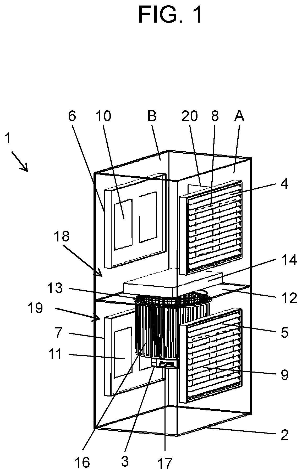
[0019]As illustrated in FIG. 1, air blowing device 1 according to the present embodiment includes hollow rectangular housing 2, and air blower 3 disposed inside housing 2. Housing 2 has first side surface A and second side surface B opposite to first side surface A. First side surface A has inlet A4 and outlet A5. Second side surface B has inlet B6 and outlet B7. Although housing 2 has a hollow rectangular tube shape in the present embodiment, the present disclosure is not limited to such an example. The shape of housing 2 may be any hollow tube shape, and may include a partially curved portion.

[0020]Inlet A4 and inlet B6 are disposed at approximately opposite positions. Outlet A5 and outlet B7 are disposed at approximately opposite positions.

[0021]Dampers which are inlet damper A8, outlet damper A9, inlet damper B10, and outlet damper B11 are respectively disposed in openings which are inlet A4, outlet A5, inlet B6, and outlet B7 so as to be able to open and close the corresponding...

second embodiment

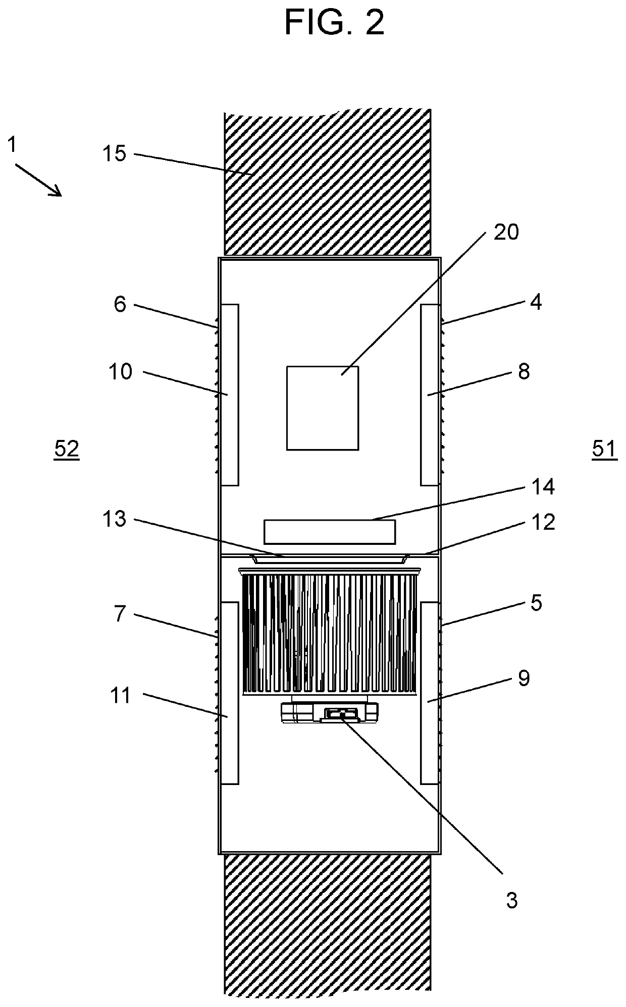
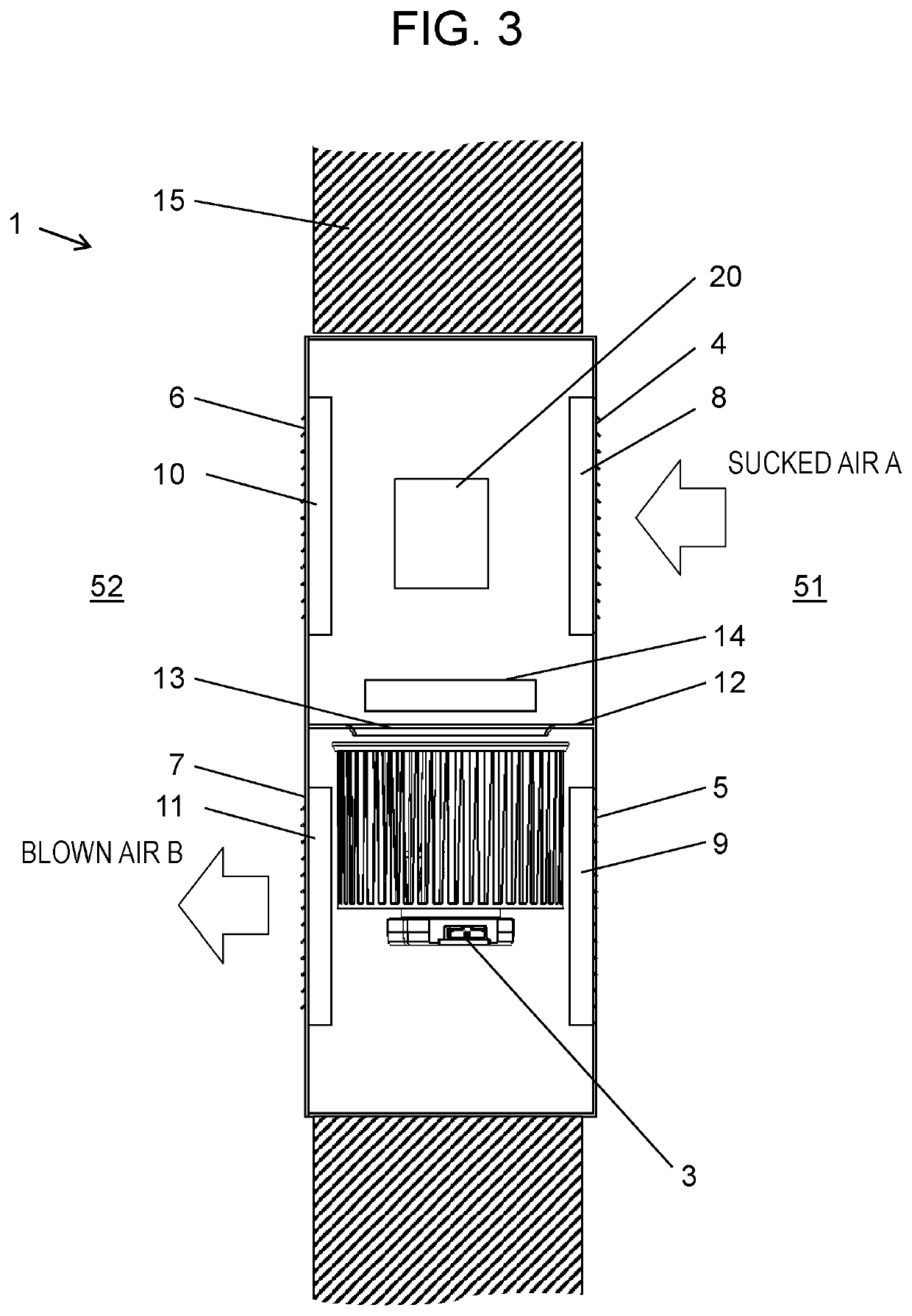
[0045]FIG. 7 illustrates a configuration of an indoor air conveying system including air blowing device 1 described in the first embodiment. In the present embodiment, dwelling 50 is a two-story house as an example for illustration. Dwelling 50 may be an apartment or a building such as an office.

[0046]As illustrated in FIG. 7, air blowing device 1 is disposed in wall 15 which partitions space A51 and space B52. Moreover, wall 15 has opening 22 which makes space A51 and space B52 communicate with each other. In wall 15, air blowing device 1 is disposed at a position higher than opening 22. In particular, it is preferable that opening 22 is disposed near the floor and air blowing device 1 is disposed near the ceiling.

[0047]Central air conditioning is performed in dwelling 50 by air conditioner 21. In other words, supply air having temperature adjusted by air conditioner 21 (cooling air or heating air) is supplied to both space A51 and space B52 on the second floor. The supply air is a...


PUM

PropertyMeasurementUnit
shapeaaaaaaaaaa
areaaaaaaaaaaa
temperatureaaaaaaaaaa

Abstract

An air blowing device includes a housing, a partition plate, an air blower, dampers, and a controller. The housing has a first side surface and a second side surface. The first side surface has inlet A and outlet A. The second side surface has inlet B and outlet B. The partition plate divides the hollow space of the housing into an upstream section and a downstream section. The upstream and downstream sections communicate with each other. The air blower conveys air from the upstream section to the downstream section. The dampers open and close the openings of inlets A and B, and outlets A and B. The controller controls air blowing of the air blower and opening and closing of each damper. Inlets A and B are disposed in the upstream section. Outlets A and B are disposed in the downstream section.

Description

TECHNICAL FIELD[0001]The present disclosure relates to an air blowing device which conveys air between adjacent spaces in a building including a plurality of spaces (rooms), such as in a home, and an indoor air conveying system using the air blowing device.BACKGROUND ART[0002]Conventionally, a ventilation system as described below is known in air conditioning in homes and the like (for example, Patent Literature (PTL) 1).[0003]Homes with a conventional ventilation system includes outlets in rooms and inlets in areas other than the rooms. The wall between a room and an adjacent area other than the room includes an opening, that is, an air distribution means. The outlet feeds outside air into the room via a means of blowing supply air. In contrast, the inlet sucks the air in the area other than the room, and exhausts the air to the outside. Since the air is exhausted from the area other than the room to the outside, the air in the room flows into the area other than the room via the a...

Claims


Application Information

Patent Timeline
Patent Type & Authority Applications(United States)
IPC IPC(8): F24F13/02F24F7/06F24F13/14F24F13/15F24F13/08F24F13/06F24F11/00
CPCF24F13/15F24F13/0236F24F7/065B01D46/448F24F13/1413F24F13/06F24F13/085F24F11/0001F24F7/013F24F7/06
Inventor FUNADA, NAOYUKI
Owner PANASONIC INTELLECTUAL PROPERTY MANAGEMENT CO LTD
Why Eureka
Try Eureka