Wireless power transmission device, wireless power reception device, and wireless charging system

a technology of wireless charging and transmission devices, applied in transformers, inductances, transportation and packaging, etc., can solve the problems of transmission devices not being able to efficiently supply power to reception power cannot be efficiently supplied to transmission devices located in directions, so as to improve the recognition distance of wireless charging and improve power efficiency.

Active Publication Date: 2020-02-13
LG ELECTRONICS INC
View PDF0 Cites 2 Cited by
  • Summary
  • Abstract
  • Description
  • Claims
  • Application Information

AI Technical Summary

Benefits of technology

[0017]According to a transmission device of the present invention as described above, a direction of a magnetic field emitted from a coil is changed from a perpendicular direction to a horizontal direction with respect to a coil by using a metallic shielding member. Therefore, a user can perform charging wirelessly even if the transmission device and a receiving device are not perpendicularly stacked with each other.
[0018]Further, according to a transmission device of the present invention, power efficiency can be improved through a first coil that emits a magnetic field having a fundamental frequency and a second coil that emits a magnetic field having a harmonic of the fundamental frequency.
[0019]Further, according to a transmission device of the present invention, a magnetic field can be concentrated and emitted through a metal member, whereby a recognition distance of wireless charging can be improved.

Problems solved by technology

On the other hand, since a transmission device (or transmitting apparatus) supplies electric power (or power) wirelessly using a magnetic field, there is a problem in that power cannot be efficiently supplied to a reception device located in a direction where density of the magnetic field is low.
Accordingly, when a reception device is not overlaid on the transmission device, the transmission device cannot efficiently supply power even when the reception device is located in the vicinity.

Method used


Image

  • Wireless power transmission device, wireless power reception device, and wireless charging system
  • Wireless power transmission device, wireless power reception device, and wireless charging system
  • Wireless power transmission device, wireless power reception device, and wireless charging system

Examples


Embodiment Construction

[0005]One aspect of the present invention is to provide a structure of a transmitting coil for wirelessly supplying power to a reception device located at a side of a transmission device.

[0006]Another aspect of the present invention is to provide a structure for improving efficiency of power supplied to a reception device located at a side of a transmission device.

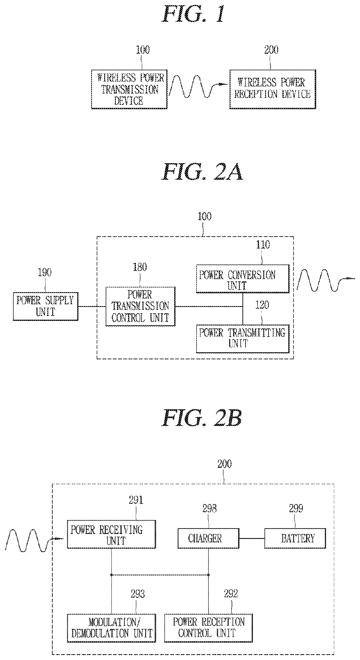
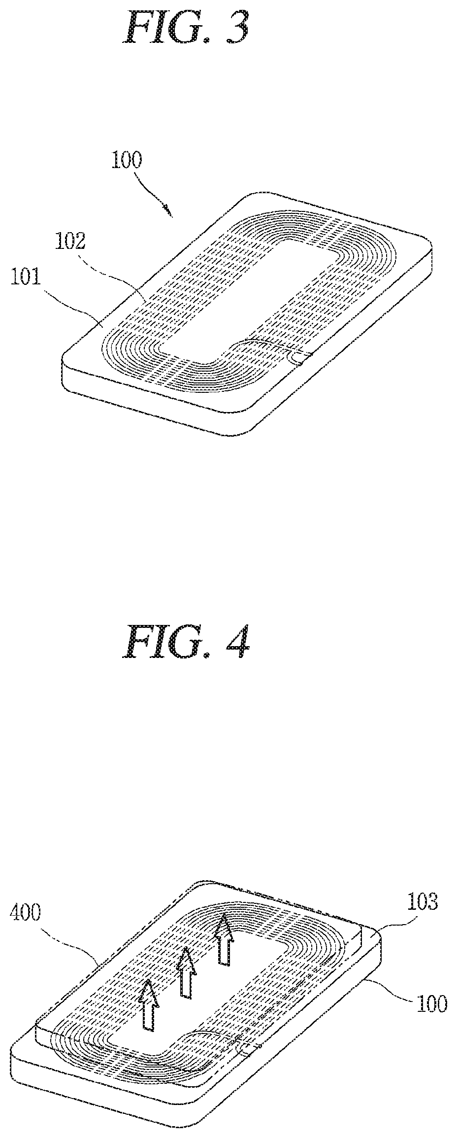
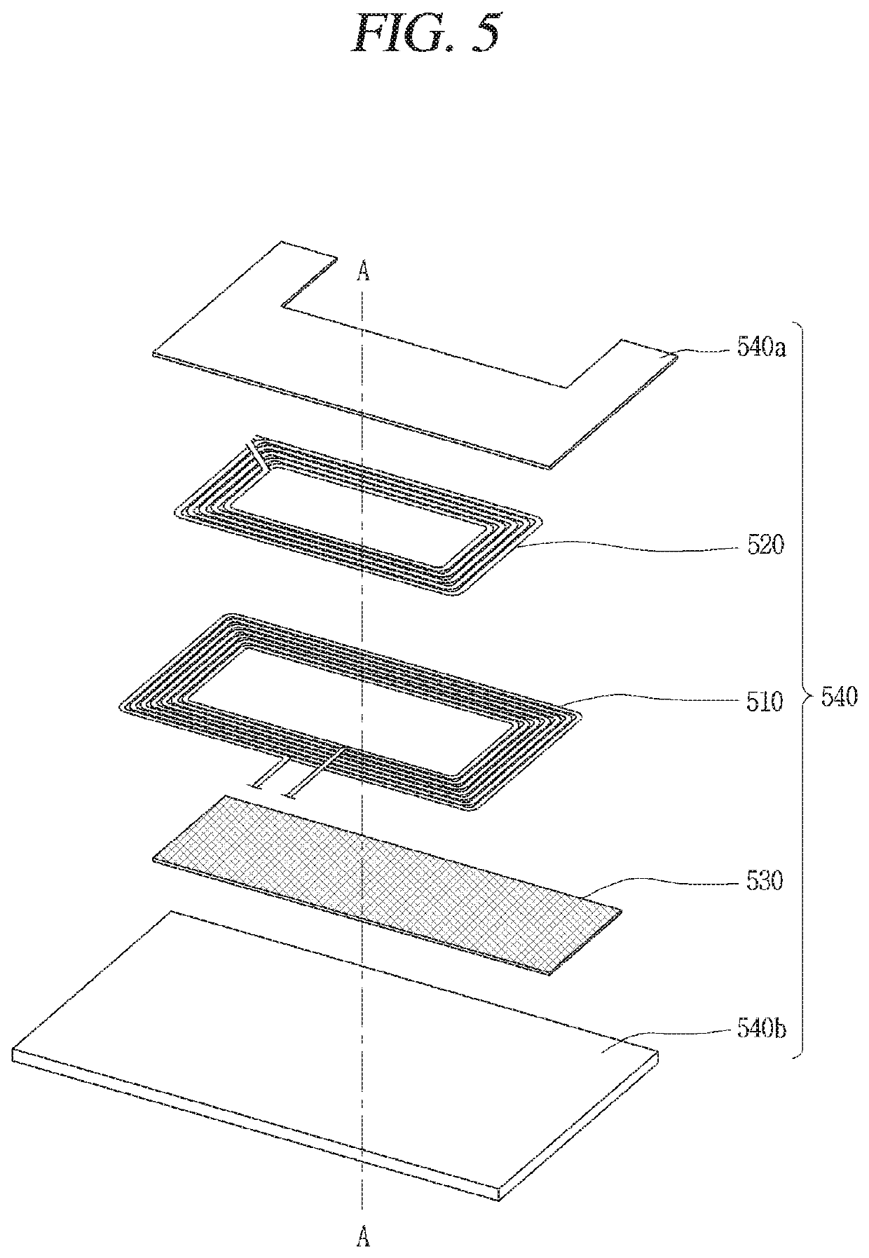
[0007]To achieve the aforementioned aspects and other advantages of the present invention, there is provided a wireless power transmission device configured to wirelessly transmit power to a wireless power reception device, the transmission device including a first coil configured to convert a current into a magnetic field, and a first metal member formed to cover at least a portion of the first coil, wherein the first metal member changes an emission direction of a magnetic field formed in the first coil so that power reaches the wireless power receiving device located at a side surface of the wireless power transmission ...


PUM

PropertyMeasurementUnit
fundamental frequencyaaaaaaaaaa
magnetic fieldaaaaaaaaaa
harmonic frequencyaaaaaaaaaa

Abstract

The present invention relates to a wireless power transmission device formed so as to wirelessly transmit power to a wireless power reception device, wherein the wireless power transmission device comprises: a first coil formed so as to transform a current into a magnetic field; and a first metal member formed so as to cover at least a portion of the first coil, and, in the present invention, the first metal member changes an emission direction of a magnetic field formed in the first coil so as to allow the power to reach the wireless power reception device which is positioned on a side surface of the wireless power transmission device.

Description

TECHNICAL FIELD[0001]The present invention relates to a method of supplying power to a wireless power reception device located at a side of a wireless power transmission device wirelessly transmitting power.BACKGROUND ART[0002]Instead of a method of supplying electrical energy to wireless power reception devices (receiving apparatuses) in a wired manner, a method of wirelessly supplying electric energy without contact has been used in recent years. A wireless power reception device that receives energy wirelessly may be driven directly by the received wireless power, or may be driven by power which is charged in a battery using the received wireless power.[0003]Wireless charging is already common in our lives. For example, a wireless charging method using electromagnetic induction is commercially utilized in electric toothbrushes, wireless coffee ports, and the like.[0004]On the other hand, since a transmission device (or transmitting apparatus) supplies electric power (or power) wi...

Claims


Application Information

Patent Timeline
Patent Type & Authority Applications(United States)
IPC IPC(8): H01F38/14H02J50/12H02J7/02
CPCH02J50/12H02J7/025H01F38/14H02J50/10H02J50/70H02J50/80H01F27/36H01F27/366H02J50/05H04B5/0037
Inventor HAN, KIWONSEO, DONGHYUNPARK, JUNHWANG, WONJI
Owner LG ELECTRONICS INC
Why Eureka
Try Eureka