
Smart touch pad device

a touch pad and smart technology, applied in the field of smart touch pad interface methods, can solve the problems of carpal tunnel, inconvenient work for the mouse, and requiring a predetermined spa

Active Publication Date: 2020-02-20
KANG TAE HO
View PDF0 Cites 1 Cited by
  • Summary
  • Abstract
  • Description
  • Claims
  • Application Information

AI Technical Summary

Benefits of technology

The present invention relates to a smart touch pad device that can perform various functions using touch gestures. It combines the functions of a mouse and a touch pad, and can perform input operations that cannot be done individually by either. It also provides a consistent user interface that can control various devices through one device and can replace various input devices with one device by using various sensing functions. Additionally, it supports a function of informing a user of call reception, text reception, or an alarm by linking with a smartphone so that the user engaged in computer work can easily recognize it.

Problems solved by technology

Accordingly, a mouse may be inconvenient in work of drawing pictures or writing characters on a monitor.
Further, using a mouse for a long period of time may cause diseases such as carpal tunnel syndrome and requires a predetermined space for up-down and left-right movements.
On the other hand, a touch pad has high touch sensitivity, so it may be suitable for work of drawing pictures or writing characters, but the width thereof is limited and the position is fixed, so it may be inconvenient to use for general pointing.
Further, specific remote controllers are used to control devices, respectively, in order to control IoT devices that are being continuously increased, but it is accompanied by inconvenience due to problems such as an increase in number of remote controller, storage and management, and inconvenience in moving.

Method used


Image

  • Smart touch pad device
  • Smart touch pad device
  • Smart touch pad device

Examples


first embodiment

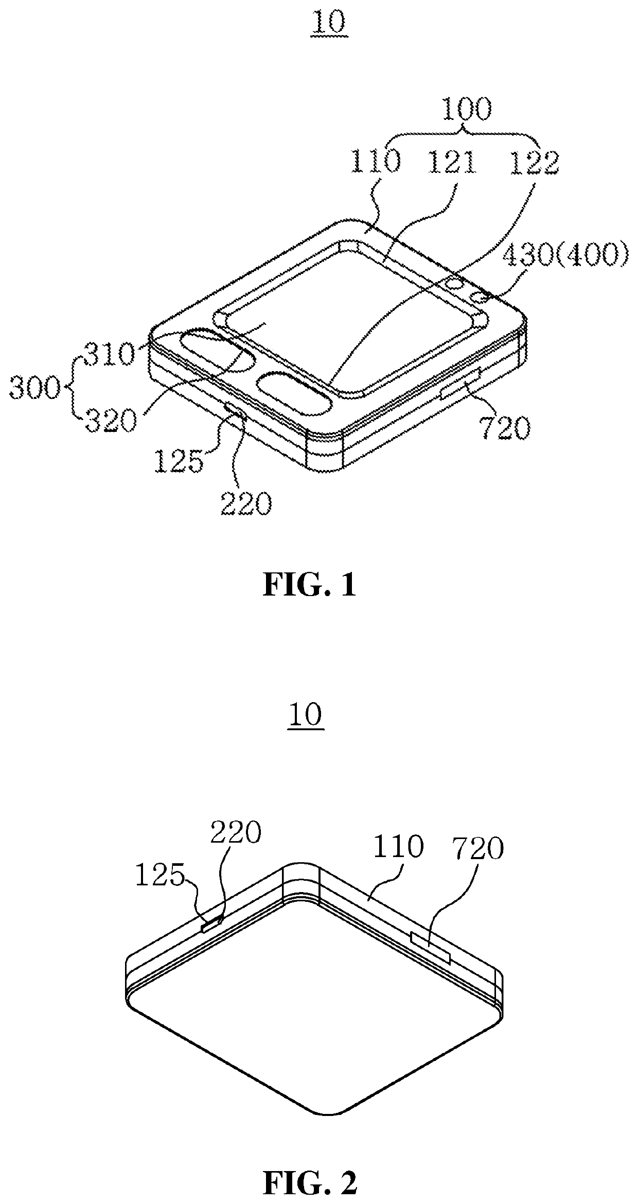
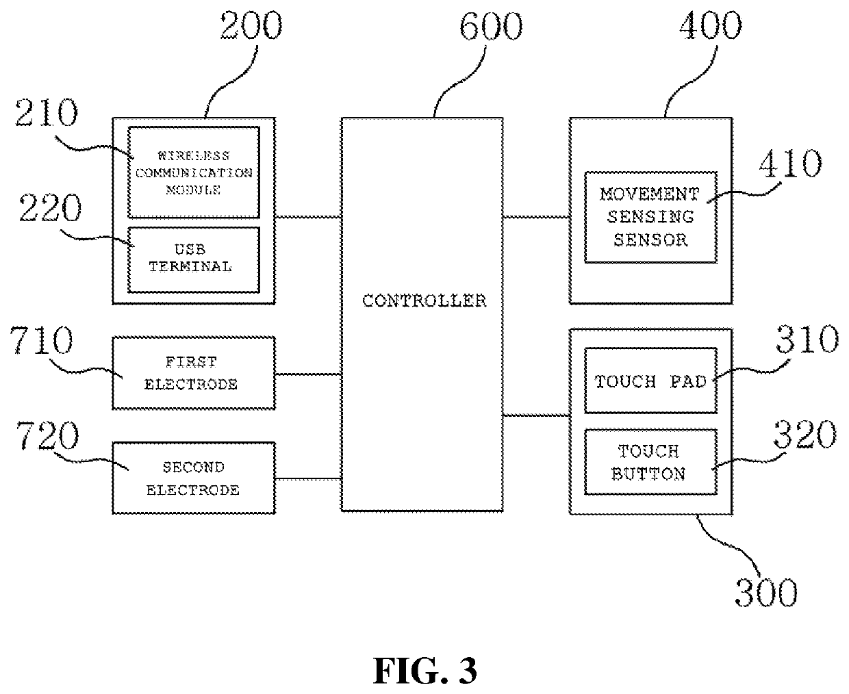
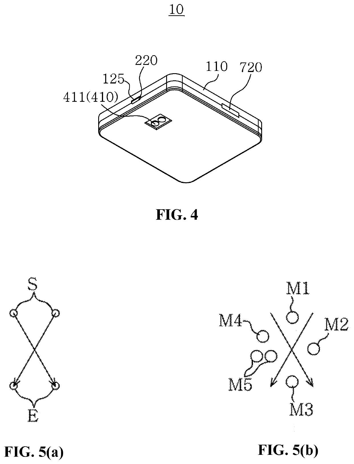
[0039]As shown in FIGS. 1 to 4, a touch pad device 10 according to the present invention may include a main body unit 100, a transceiver unit 200, a touch pad unit 300, a mouse unit 400, and a controller 600.

[0040]In detail, the main body unit 100 may be provided in a housing shape that a user can hold by hand. In this embodiment, the main body unit 100 may be configured as a flat hexahedron-shaped case 110. However, the main body unit 100 is not limited thereto and, obviously, may be changed in various shapes that a user can conveniently hold by hand.

[0041]A pad groove 121 in which a touch pad 310 of the touch pad unit 300 is positioned and a pair of touch grooves 122 exposing a touch button 320 may be formed on one surface (e.g., the top surface) of the main body unit 100. Further, on one surface of the main body unit 100, a plurality of slip tabs 430 may be disposed and spaced apart from each other close to an edge of the main body unit 100.

[0042]A first electrode 710 and a secon...

second embodiment

[0107]FIG. 9 is a block diagram showing the main configuration of a touch pad device according to the present invention.

[0108]As shown in FIG. 9, a touch pad device according to a second embodiment of the present invention may include a main body unit 100, a transceiver unit 200, a touch pad unit 300, a mouse unit 400, a controller 600, and a horizontal sensor 500.

[0109]The touch pad device according to the second embodiment may be similar to or substantially the same as the configuration described in the first embodiment in other configuration except for the horizontal sensor 500, so the above description of components and operations may be omitted and similar reference numerals may be given to similar components.

[0110]The horizontal sensor 500 can sense the state when the main body unit 100 is moved horizontally with respect to the ground. The horizontal sensor 500 may be configured as a sensor different from the movement sensing sensor 410 stated in the first embodiment. For exam...

third embodiment

[0114]FIG. 10 is a perspective view showing a touch pad device according to the present invention. Parts that are not shown in this figure are the components the same as or similar to those of the previous embodiments and repeated components and reference numerals are omitted. In FIG. 10, (a) shows the front surface of the touch pad device 10 and (b) shows the rear surface of the touch pad device 10.

[0115]A touch pad unit 300 may be disposed on the front surface of the touch pad device 10. The touch pad unit 300 may include a touch pad 310 that recognizes a touch signal generated by contact of a user. A pair of mouse buttons 421 and 422 and a wheel button 423 may be disposed at an end of the touch pad 310. The pair of mouse buttons 421 and 422 may be disposed on one surface of the main body unit 100 such that an execution signal is input by a push of a user. The wheel button 423 is disposed between the pair of mouse buttons 421 and 422 and can sense a swipe by a user.

[0116]The pair ...


PUM


Abstract

A smart touch pad device includes: a main body unit; a touch pad unit that is disposed on the main body unit to recognize a touch signal and a motion signal generated by contact of a user; a mouse unit that recognizes an operation signal generated by movement of the main body unit; a controller that extracts movement information from a touch signal or an operation signal or extract motion information that can perform a predetermined function from a touch signal; and a transceiver unit that transmits / receives movement information and motion information to / from a computer or a mobile communication device.

Description

BACKGROUND OF THE INVENTIONField of the Invention[0001]The present invention relates to a smart touch pad interface method and an apparatus thereof and, more particularly, to a smart touch pad interface method that can support a touch pad function and a mouse function as a pointing device, and can perform a remote control function on a touch pad on the basis of a touch gesture, and an apparatus thereof.Description of the Related Art[0002]In general, a mouse, which is an input device for executing programs in computers, can move a pointer (cursor) on a monitor by moving or can execute programs related to icons on which a pointer is positioned when a mouse button is pushed.[0003]Notebooks generally use a touch pad integrally installed with the notebooks as an input device due to the demand of downsizing. A touch pad can generate a movement of a pointer (cursor) on a monitor by converting a touch by a finger into electrical signals. Similar to a mouse, a touch pad has a touch button en...

Claims


Application Information

Patent Timeline
Patent Type & Authority Applications(United States)
IPC IPC(8): G06F3/044G06F3/041
CPCG06F3/0416G06F3/044G06F3/0412G06F3/04883G06F3/03543G06F3/0317G06F3/03547G06F3/0383G06F3/0395G06F3/017G06F3/0362H04Q9/00H04Q2209/40G06F3/04164
Inventor KANG, TAE HO
Owner KANG TAE HO
Learn More