Cover for blood pressure meter, and blood pressure meter

a blood pressure meter and cover technology, applied in the field of blood pressure meter covers, can solve the problems of bulky blood pressure meter and the inability to remove the cover from the main body, and achieve the effect of small siz

Pending Publication Date: 2020-03-12
OMRON HEALTHCARE CO LTD
View PDF0 Cites 1 Cited by
  • Summary
  • Abstract
  • Description
  • Claims
  • Application Information

AI Technical Summary

Benefits of technology

[0006]Hence, an object of the present invention is to provide a cover for a blood pressure meter that can accommodate a cuff belt, and is removable from a main body of the blood pressure meter.
[0018]Additionally, the panel cover region and the storage cover region capable of being “opened” with respect to the front panel and the tray region means that the panel cover region and the storage cover region can be separated from the front panel and the tray region, and the front panel and the tray region can become accessible by the user. The panel cover region and the storage cover region capable of being “closed” with respect to the front panel and the tray region means that the panel cover region and the storage cover region can come close to the front panel and the tray region, and cover the front panel and the tray region.

Problems solved by technology

However, in the above blood pressure meter, the cover is attached to the main body of the blood pressure meter with the hinge, and the cover cannot be removed from the main body.
For this reason, there has been a problem that the blood pressure meter becomes bulky because of the cover.

Method used


Image

  • Cover for blood pressure meter, and blood pressure meter
  • Cover for blood pressure meter, and blood pressure meter
  • Cover for blood pressure meter, and blood pressure meter

Examples


modification 1

[0084](Modification 1)

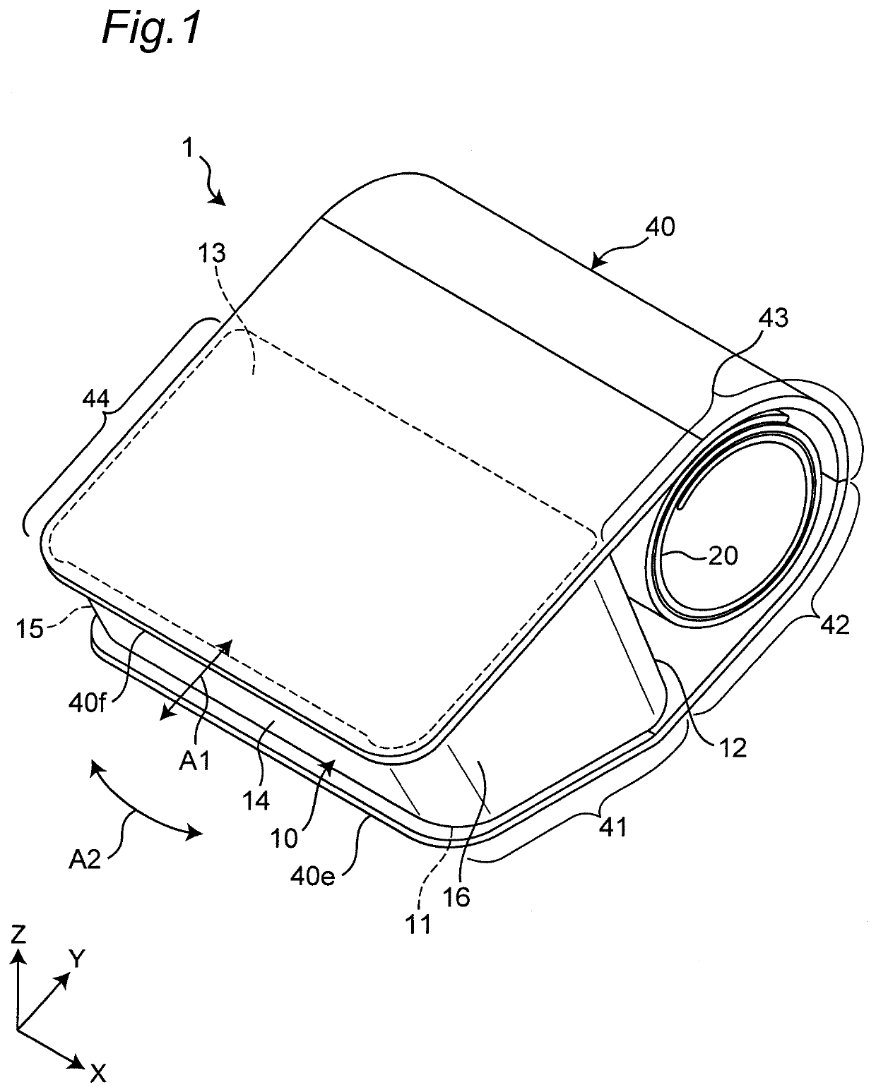
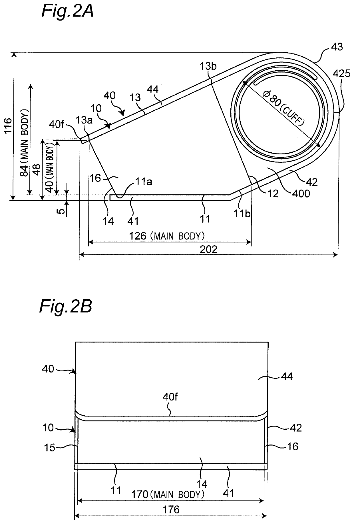
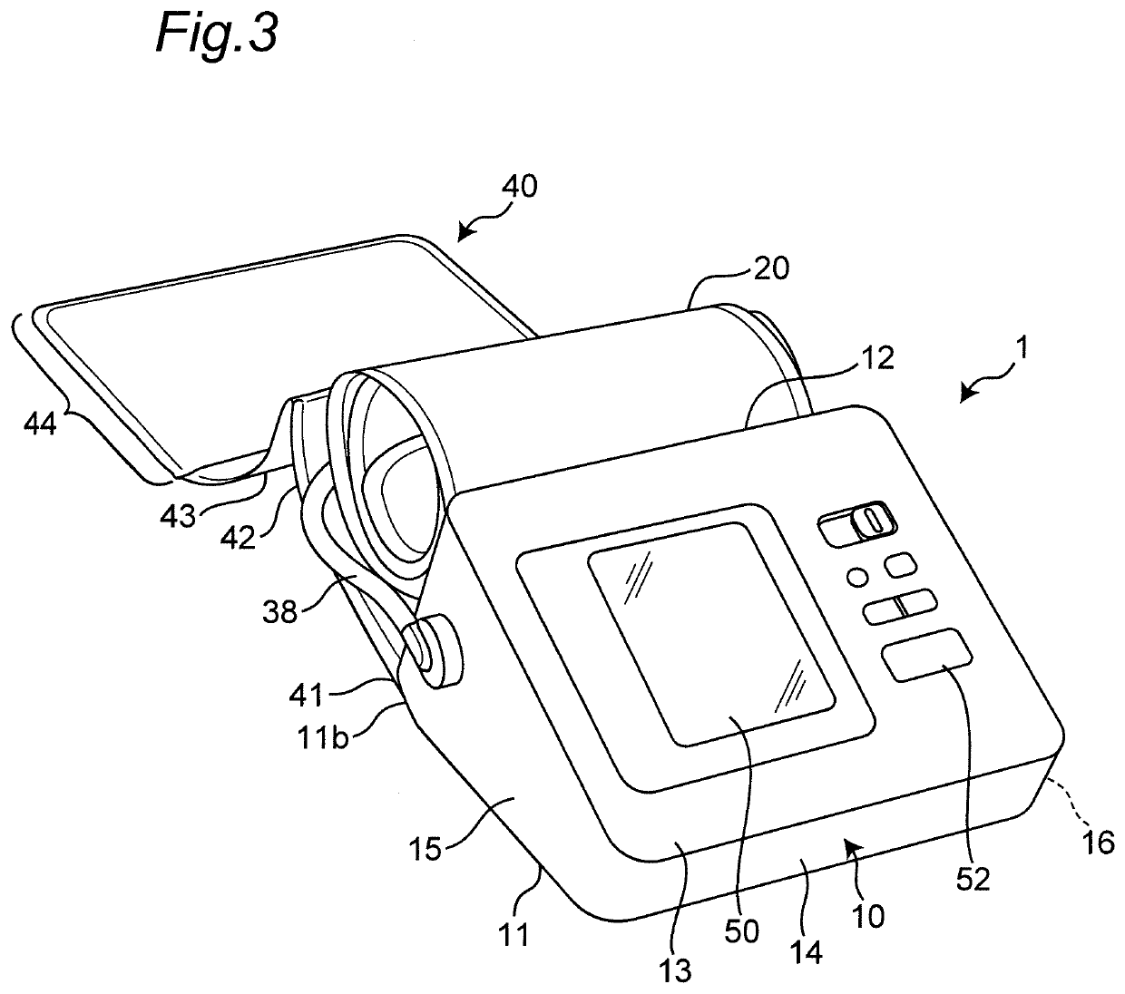
[0085]FIGS. 9 to 11 show a modification of the structure in which the cover for a blood pressure meter 40 is detachably attached to the main body 10. In this example, the first hook-and-loop fasteners 61 and 62 and the second hook-and-loop fasteners 63 and 64 are omitted (the same applies to Modifications 2 and 3 described later).

[0086]In this example, as shown in FIG. 9, a main body (indicated by reference numeral 10A) has a pair of receiving holes 65 and 66 on both sides in the width direction (direction X shown in FIG. 1) on a rear edge portion 11b of the bottom surface 11. These receiving holes 65 and 66 are formed in a cylindrical shape. On the other hand, a cover for a blood pressure meter (indicated by reference numeral 40A) has cylindrical projections 67 and 68 dimensioned so as to closely fit into the receiving holes 65 and 66, respectively, in locations in a coupling region (indicated by reference numeral 41′) corresponding to the receiving holes 65 a...

modification 2

[0089](Modification 2)

[0090]FIGS. 12 to 14 show another modification of the structure in which the cover for a blood pressure meter 40 is detachably attached to the main body 10.

[0091]In this example, as shown in FIG. 12, a main body (indicated by reference numeral 10B) has a pair of right and left receiving holes 71 and 73 on the rear end side and a receiving hole 72 disposed at the center on the front end side in a rear edge portion 11b of a bottom surface 11. These receiving holes 71, 72, and 73 are configured as horizontally long openings (openings whose width dimension is longer than the depth dimension). On the other hand, a cover for a blood pressure meter (indicated by reference numeral 40B) has hooks 74, 75, and 76 with an L-shaped cross-section dimensioned so as to engage with the receiving holes 71, 72, and 73, respectively, in locations in a coupling region (indicated by reference numeral 41′) corresponding to the receiving holes 71, 72, and 73. The front end of the cent...

modification 3

[0095](Modification 3)

[0096]FIGS. 16 to 18 show still another modification of the structure in which the cover for a blood pressure meter 40 is detachably attached to the main body 10.

[0097]In this example, as shown in FIG. 16, a main body (indicated by reference numeral 10D) has a substantially rectangular battery passage opening 123 formed in a bottom surface 11. In this example, the battery passage opening 123 is disposed in a position at the substantial center in the width direction (direction X shown in FIG. 1) and in contact with a rear edge portion 11b in the longitudinal direction (direction Y shown in FIG. 1) of a bottom surface 11. The battery passage opening 123 is an opening for inserting a battery into a battery storage portion (not shown) built in the main body 10 from the outside, or removing it. An original battery lid 120 as a first battery lid is detachably fitted and attached to the battery passage opening 123. Specifically, the battery lid 120 has a substantially...


PUM


Abstract

In the cover for a blood pressure meter according to the invention, a coupling region that is detachably attached to a bottom surface of a main body is provided on one end. A tray region that is disposed so as to face a back surface of the main body and receives an accommodated cuff belt is connected to the coupling region. A panel cover region capable of covering a front panel of the main body is provided on the other end. A storage cover region that connects the tray region and the panel cover region is provided. In a cover-coupled state where the coupling region is detachably attached to the bottom surface of the main body, the panel cover region and the storage cover region are configured to be openable and closable with respect to the front panel and the tray region.

Description

CROSS-REFERENCE TO RELATED APPLICATION[0001]This is a continuation application of International Application No. PCT / JP2018 / 021004, with an International filing date of May 31, 2018, which claims priority of Japanese Patent Application No. 2017-135546 filed on Jul. 11, 2017, the entire content of which is hereby incorporated by reference.TECHNICAL FIELD[0002]The present invention relates to a cover for a blood pressure meter, and more particularly to a cover for a blood pressure meter that can accommodate a cuff belt.[0003]The present invention also relates to a blood pressure meter having such a cover for a blood pressure meter.BACKGROUND ART[0004]Conventionally, as a blood pressure meter having this type of cover for a blood pressure meter, there has been known a structure in which a substantially plate-like cover capable of covering an upper surface (front panel) of a main body of the blood pressure meter is attached to the back side (back surface) of the main body through a hinge...

Claims


Application Information

Patent Timeline
Patent Type & Authority Applications(United States)
IPC IPC(8): A61B50/00A61B5/022A61B5/021
CPCA61B2050/0053A61B5/022A61B50/00A61B5/02141A61B2050/0056A61B2050/0079A61B2050/008A61B5/02233A61B2560/0443A61B2562/247
Inventor OGIHARA, TSUYOSHIINAMI, YOSHIKAZUNOGUCHI, SOTSURUTA, SHUJI
Owner OMRON HEALTHCARE CO LTD
Why Eureka
Try Eureka