
Hydraulic Block for a Hydraulic Assembly of a Slip Control System of a Hydraulic Vehicle Brake System

Active Publication Date: 2020-03-26
ROBERT BOSCH GMBH
View PDF43 Cites 3 Cited by
  • Summary
  • Abstract
  • Description
  • Claims
  • Application Information

AI Technical Summary

Benefits of technology

The invention describes a hydraulic block for a vehicle that has a capacity for easier venting of a hydraulic accumulator. The accumulator can be located in the hydraulic block, which is typically installed vertically in the engine compartment. The invention also provides an option of arranging the accumulator to cover one or more solenoid valves, which are used in the slip control system. This arrangement allows for a short coupling of the accumulator to the solenoid valves, resulting in a short venting path. Overall, the invention enables improved performance and efficiency of the hydraulic system in vehicles.

Problems solved by technology

This results in a short coupling of the at least one hydraulic accumulator to at least one outlet valve and a short venting path.

Method used


Image

  • Hydraulic Block for a Hydraulic Assembly of a Slip Control System of a Hydraulic Vehicle Brake System

Examples


Embodiment Construction

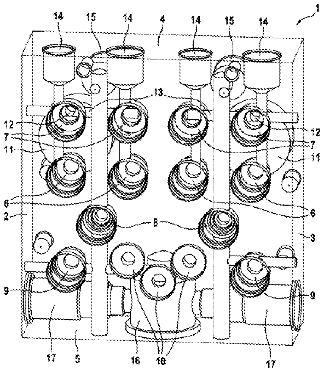
[0019]The hydraulic block 1 according to the invention, which is drawn transparently, is provided for a hydraulic assembly of a slip control system of a hydraulic vehicle brake system which is otherwise not illustrated. Such slip control systems are, for example, antilock brake systems, traction control systems and / or vehicle dynamics management / electronic stability programs, for which the abbreviations ABS, TCS, VDM / ESP are commonly used. The hydraulic block 1 is a box-shaped metal block. It has a rectangular base side and a congruent cover side, opposite the base side, which are referred to here as accumulator side and as valve side 2, two mutually opposing longitudinal sides 3 and two likewise mutually opposing transverse sides, which are referred to here as connection side 4 and as motor side 5. The accumulator side and the valve side 2 are the two large sides of the hydraulic block 1. The longitudinal sides 3 do not have to be longer than the transverse sides.

[0020]The hydrauli...


PUM


Abstract

A hydraulic block of a slip control system of a hydraulic vehicle brake system includes receptacles for the hydraulic accumulator and receptacles for outlet valves arranged on opposite sides of each other in the hydraulic block. The sides of the hydraulic block, which comprise the receptacles for the outlet valves and the hydraulic accumulators, are connected to one another by bores perpendicular thereto.

Description

[0001]The invention relates to a hydraulic block for a hydraulic assembly of a slip control system of a hydraulic vehicle brake system having the features of the precharacterizing clause of claim 1.[0002]Slip control systems are, for example, antilock brake systems, traction control systems and / or vehicle dynamics management / electronic stability programs, for which the abbreviations ABS, TCS, VDM / ESP are commonly used. Such slip control systems of hydraulic vehicle brake systems are known from automobiles and motorcycles and are not explained in more detail here.PRIOR ART[0003]The core of such slip control systems is a hydraulic assembly, which has a hydraulic block which is equipped with hydraulic components of the slip control system and is connected to a master brake cylinder by brake lines and to which one or more hydraulic wheel brakes are connected by brake lines. Hydraulic components are, amongst other things, solenoid valves, hydraulic pumps (most commonly piston pumps), non...

Claims


Application Information

Patent Timeline
IPC IPC(8): B60T8/40B60T8/48F15B1/04
CPCB60T8/4836F15B1/04B60T8/4031B60T17/04B60T17/043F15B13/0814F15B2211/625B60T8/368F15B13/08B60T13/14B60Y2400/81
Inventor ZANDER, THOMASLOEFFLER, MICHAEL
Owner ROBERT BOSCH GMBH
Learn More