
Communication system

Active Publication Date: 2020-04-23
YAZAKI CORP
View PDF0 Cites 1 Cited by
  • Summary
  • Abstract
  • Description
  • Claims
  • Application Information

AI Technical Summary

Benefits of technology

The present invention aims to provide a communication system that can shorten the time it takes to set an ID and reduce errors in settings. By eliminating the need to allocate an ID each time a slave device is connected, the ID setting time is reduced and the likelihood of errors is minimized.

Problems solved by technology

However, there was a problem that setting the ID for each connection of the slave device requires a long time for the ID setting.
There was also the problem that since the order of ID to be sent by the master device to the slave device is fixed, the ID different from the original is set if the connection order to the in-vehicle LAN of the slave device is different.

Method used


Image

  • Communication system
  • Communication system
  • Communication system

Examples


Embodiment Construction

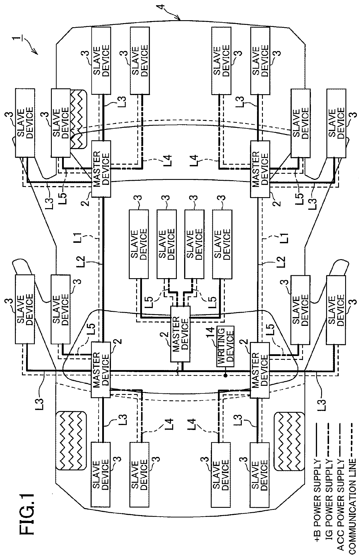
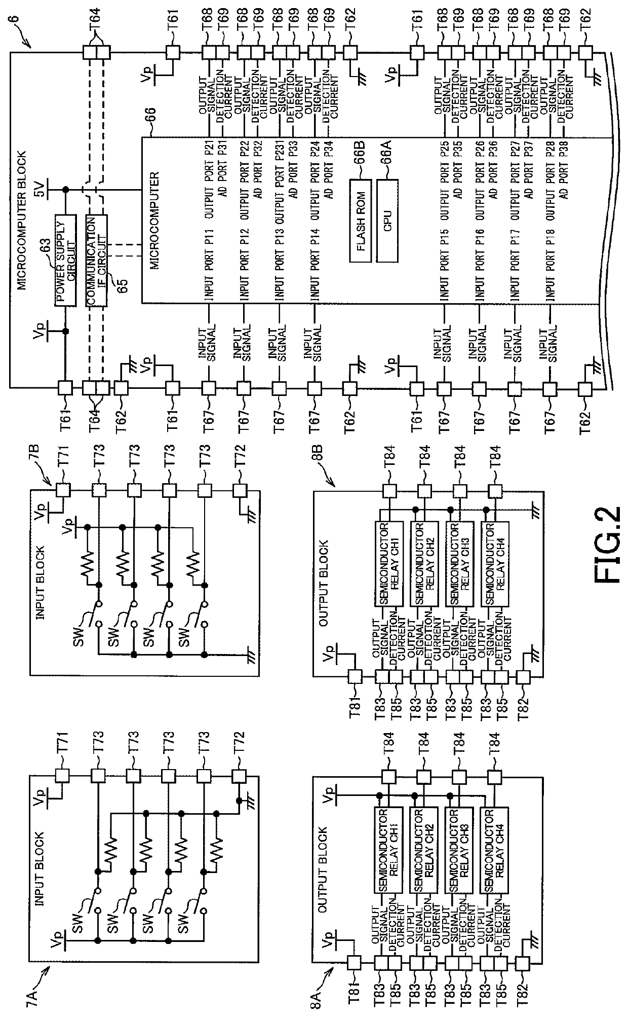
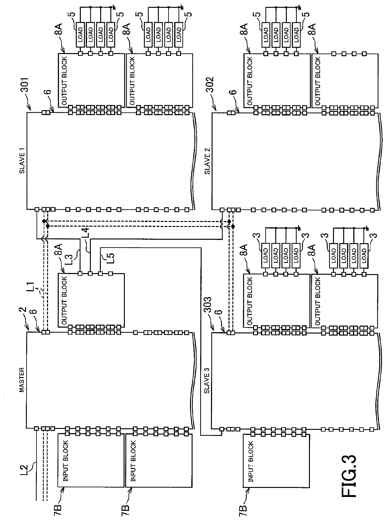
[0020]Hereinafter, an embodiment of the present invention will be described based on FIGS. 1 and 2. FIG. 1 is a block diagram showing an in-vehicle network as a communication system of the present invention. FIG. 2 is a block diagram showing a master device 2 and a slave device 3 that make up the in-vehicle network 1 shown in FIG. 1. FIG. 3 is a block diagram showing the in-vehicle network shown in FIG. 1 configured to combine the blocks shown in FIG. 2.

[0021]An in-vehicle network 1 shown in FIG. 1 is mounted on a vehicle 4. The in-vehicle network 1 includes a plurality of master devices 2 and a plurality of slave devices 3 (which may be described as slave devices 301-301 as shown in FIG. 3). The plurality of master devices 2 is arranged in each area in a vehicle 4. In the present embodiment, the master device 2 is respectively arranged on front right side (FR-RH), front left side (FR-LH), front center (FR-CENTER), rear right side (RR-RH), and rear left side (RR-LH) in five places i...


PUM


Abstract

A communication system capable of shortening a setting time of an ID and reducing an incorrect setting is provided. A writing device sequentially transmits an ID of a plurality of slave devices after transmitting of the ID of a master device. The master device includes a plurality of semiconductor relays provided for each of the plurality of master slave devices for supplying power to the corresponding slave devices. The master device receives the ID of the master device from the writing device, and sets it as its own ID. The master device, every time the ID of the plurality of slave devices is received from the writing device after setting the ID of its own, turns on the semiconductor relays in order. The plurality of slave devices sets the ID received after power supply as its own ID.

Description

BACKGROUND OF THE INVENTIONField of the Invention[0001]The present invention relates to a communication system.Description of the Related Art[0002]A vehicle such as a passenger car and a freight car is equipped with various loads such as a lamp and a power window. Then, there has been proposed a technology for controlling the loads using communication with a slave device to which a plurality of loads is connected and a master device controlling the plurality of slave devices.[0003]In the above technology, the plurality of slave devices to which the plurality of loads is respectively connected needs to be set an ID.[0004]As a method of setting the above-mentioned ID, for example, the one described in Patent Literature 1 has been proposed. In the ID setting method described above, each time a slave device whose ID is not set is connected to the in-vehicle LAN, the master device sends an ID to the slave device, and the slave device stores the ID.[0005]However, there was a problem that ...

Claims


Application Information

Patent Timeline
IPC IPC(8): H04L12/403H04L12/40H04L12/12
CPCH04L12/40019H04L12/403H04L2012/40273H04L12/12H04L67/12H04B1/3822G06F13/4282
Inventor NAKAMURA, YOSHIHIDE
Owner YAZAKI CORP
Learn More