
DC-DC converter with pull-up and pull-down currents based on inductor current

Active Publication Date: 2018-01-09
MEDIATEK INC
View PDF9 Cites 0 Cited by
  • Summary
  • Abstract
  • Description
  • Claims
  • Application Information

AI Technical Summary

Benefits of technology

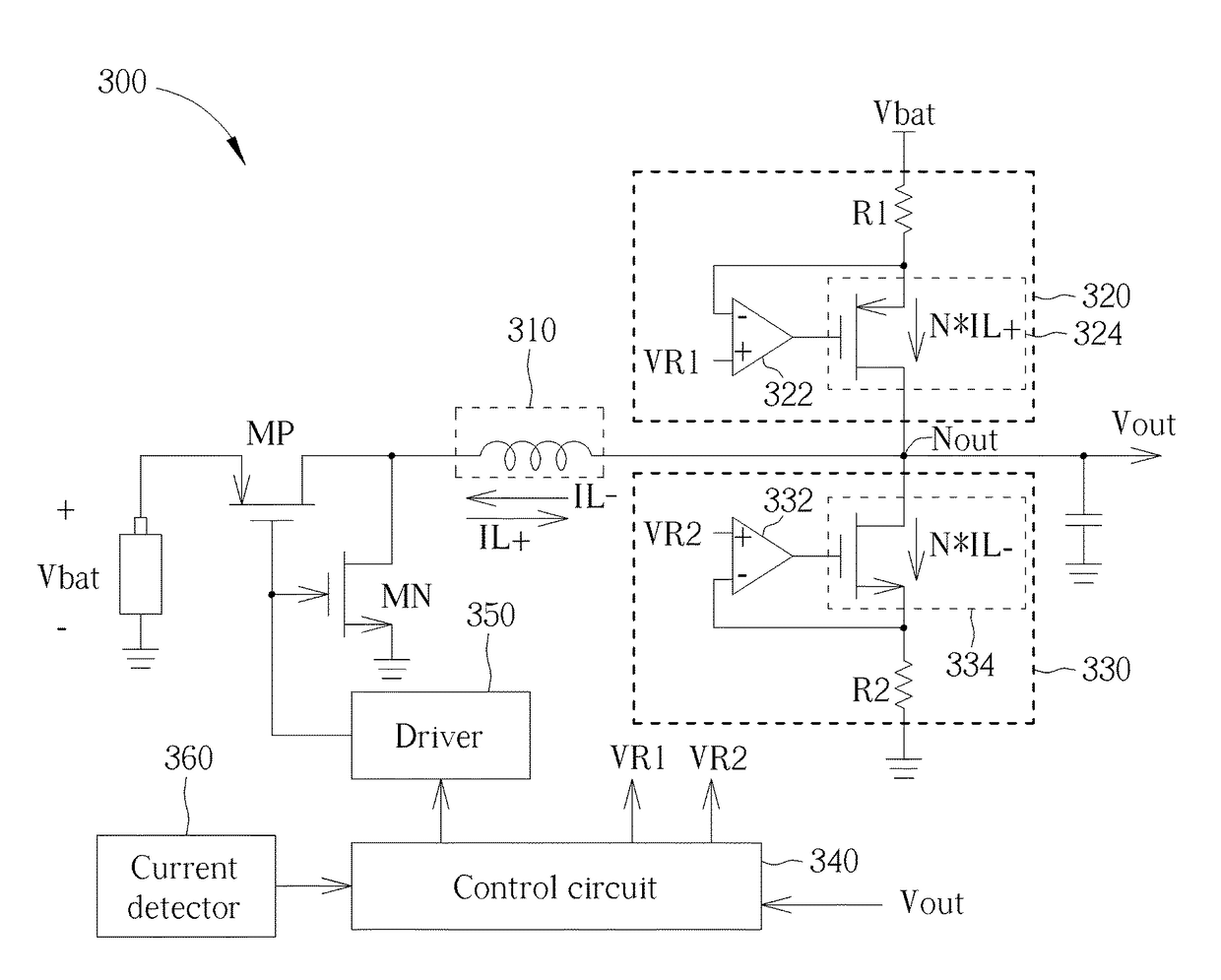
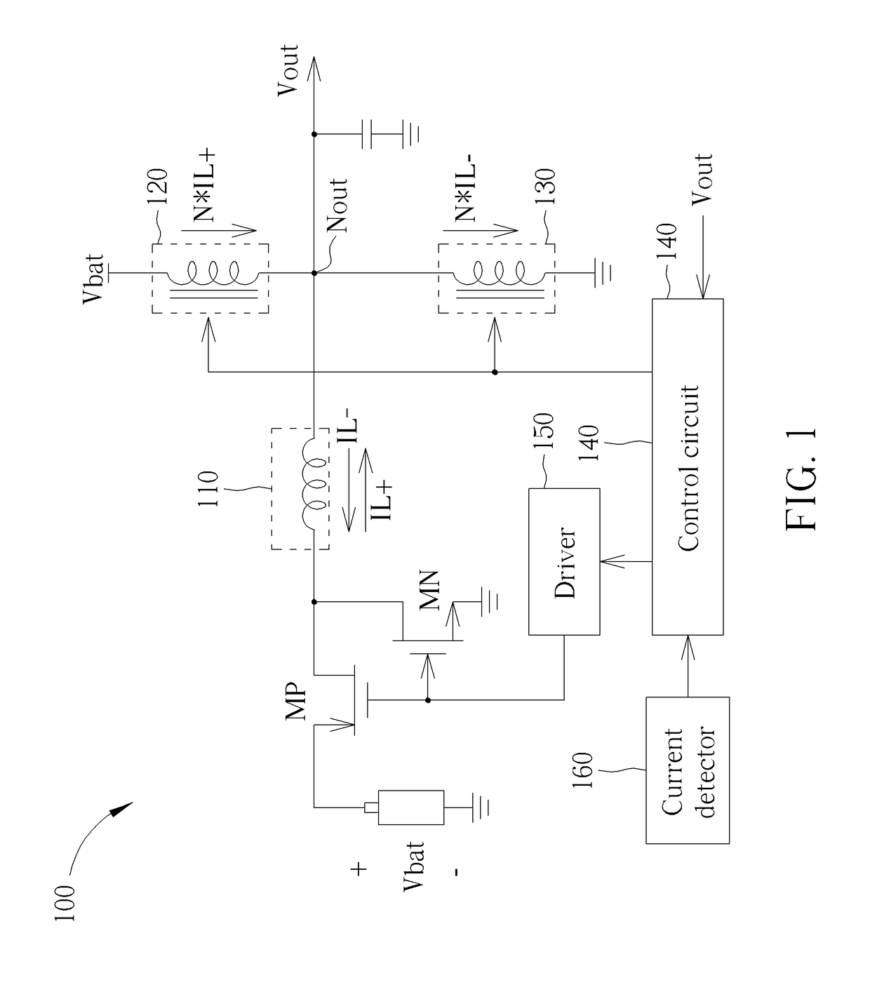
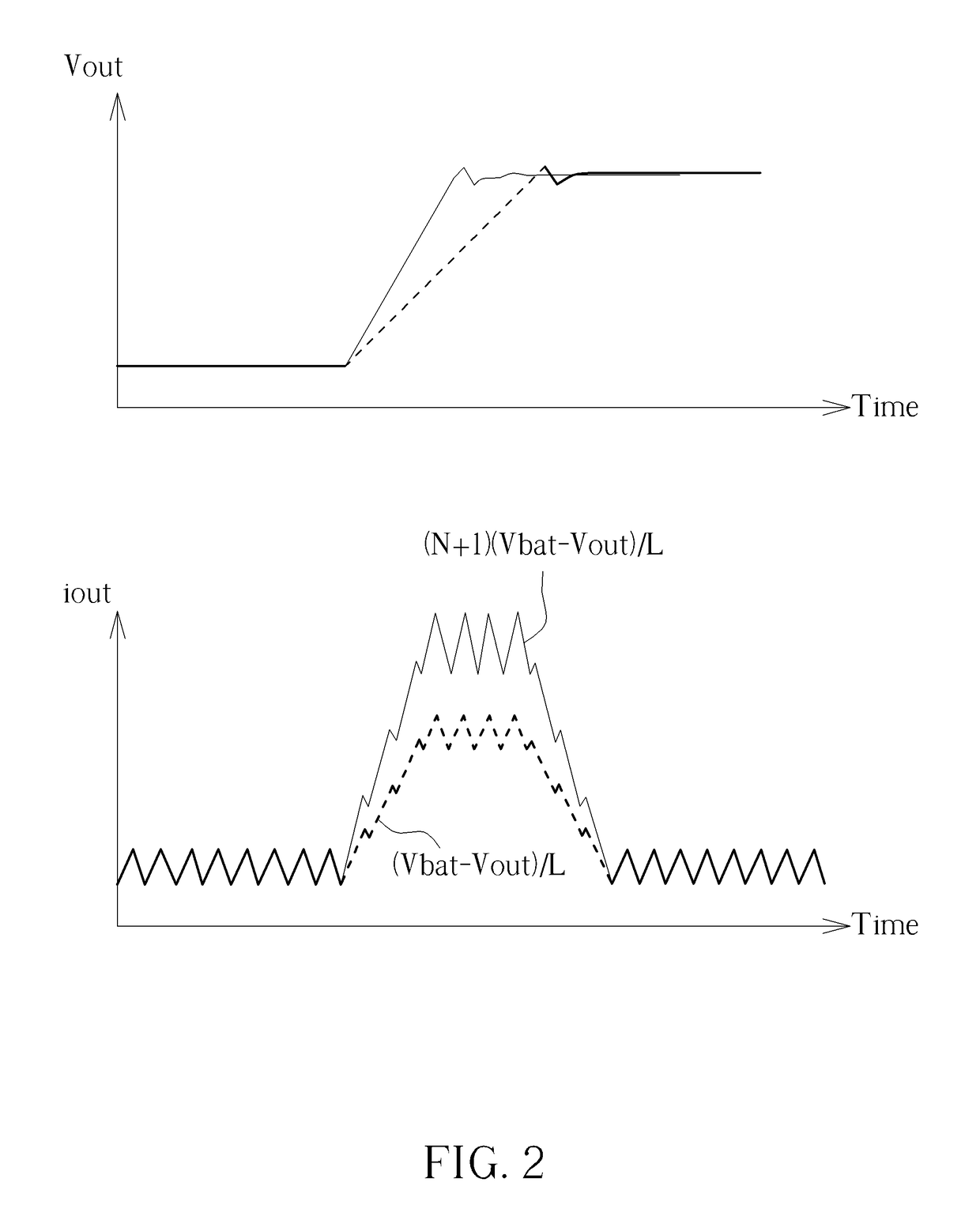
The present invention aims to provide a DC-DC converter with an additional charging path to speed up the setting time. The current provided by this path is determined based on the inductor current within the converter. The technical effect is to overcome the problem of slow setting times in DC-DC converters and speed up the charging process.

Problems solved by technology

However, the smaller inductance may cause a large ripple on the output voltage.
Therefore, the tradeoff between the settling time and the ripple becomes a problem to a designer.
Conventional art provides a converter having additional charging path to shorten the settling time, however, the response of the circuits is generally difficult to control due to the inappropriate setting of the current provided by this additional charging path.

Method used


Image

  • DC-DC converter with pull-up and pull-down currents based on inductor current
  • DC-DC converter with pull-up and pull-down currents based on inductor current
  • DC-DC converter with pull-up and pull-down currents based on inductor current

Examples


Embodiment Construction

[0011]Certain terms are used throughout the following description and claims to refer to particular system components. As one skilled in the art will appreciate, manufacturers may refer to a component by different names. This document does not intend to distinguish between components that differ in name but not function. In the following discussion and in the claims, the terms “including” and “comprising” are used in an open-ended fashion, and thus should be interpreted to mean “including, but not limited to . . . .” The terms “couple” and “couples” are intended to mean either an indirect or a direct electrical connection. Thus, if a first device couples to a second device, that connection may be through a direct electrical connection, or through an indirect electrical connection via other devices and connections.

[0012]Please refer to FIG. 1, which is a diagram illustrating a DC-DC converter 100 according to one embodiment of the present invention. As shown in FIG. 1, the DC-DC conv...


PUM


Abstract

A DC-DC converter includes an inductor, a switch module, a pull-up circuit and a pull-down circuit. The inductor has a first node and a second node, and the second node is coupled to an output node of the DC-DC converter. The switch module is arranged for selectively connecting an input voltage or a ground voltage to the first node of the inductor according to a driving signal. The pull-up circuit is arranged for selectively providing a first current to the output node of the DC-DC converter. The pull-down circuit is arranged for selectively sinking a second current from the output node of the DC-DC converter. In addition, at least one of the first current provided by the pull-up circuit and the second current sunk by the pull-down circuit is determined based on an inductor current flowing through the inductor.

Description

CROSS REFERENCE TO RELATED APPLICATIONS[0001]This application claims the priority of U.S. Provisional Application No. 62 / 288,493, filed on Jan. 29, 2016, which is included herein by reference in its entirety.BACKGROUND[0002]When a DC-DC converter is used to convert an input voltage to a desired output voltage, a settling time (transition time) is preferred to be as short as possible. The settling time is related to an inductance of an inductor within the DC-DC converter, and the smaller inductance results in a shorter setting time. However, the smaller inductance may cause a large ripple on the output voltage. Therefore, the tradeoff between the settling time and the ripple becomes a problem to a designer.[0003]Conventional art provides a converter having additional charging path to shorten the settling time, however, the response of the circuits is generally difficult to control due to the inappropriate setting of the current provided by this additional charging path.SUMMARY[0004]I...

Claims


Application Information

Patent Timeline
IPC IPC(8): H02M3/158H02M1/08H02M3/156G05F1/618H02M1/00
CPCH02M3/158H02M1/08H02M2003/1566H02M2001/0009H02M2001/0045G05F1/618H02M1/088H02M3/1563H02M1/0003H02M3/1566H02M1/0009H02M1/0045
Inventor LIN, SHIH-MEIKUAN, CHIEN-WEILEE, CHIEN-LUNGMENG, CHE-HAO
Owner MEDIATEK INC
Learn More