Liquid Control Valve Assembly Having Multiple Outlets for Balancing Output Liquid

Active Publication Date: 2020-06-18
TSOU ERIC
View PDF27 Cites 0 Cited by
  • Summary
  • Abstract
  • Description
  • Claims
  • Application Information

AI Technical Summary

Benefits of technology

[0021]In one embodiment of the present invention, the main casing further defines a high pressure relief valve chamber therein. The liquid control valve assembly of the present invention preferably includes a high pressure relief valve disposed in the high pressure relief valve chamber and having an end portion protruding outwardly to an exterior of the main casing and the other end portion extending into the split-flow path such that the high pressure relief valve is capable of reducing a liquid pressure within the split-flow path.
[0022]The advantages provided by the liquid control v

Problems solved by technology

Some disadvantages resulted from the use of the prior art control valve reside in firstly: the liquid flow or the flow velocity of the liquid flowing from the liquid source to two external device is not stable, the liquid flow and

Method used


Image

  • Liquid Control Valve Assembly Having Multiple Outlets for Balancing Output Liquid
  • Liquid Control Valve Assembly Having Multiple Outlets for Balancing Output Liquid
  • Liquid Control Valve Assembly Having Multiple Outlets for Balancing Output Liquid

Examples


Embodiment Construction

[0035]The accompanying drawings are included to provide a further understanding of the invention, and are incorporated in and constitute a part of this specification. The drawings illustrate embodiments of the invention and, together with the description, serve to explain the principles of the invention.

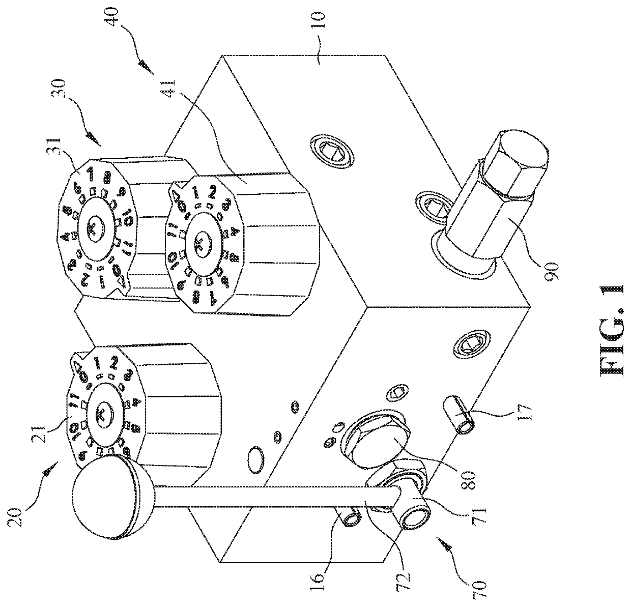
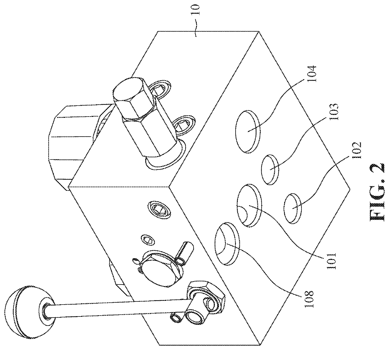
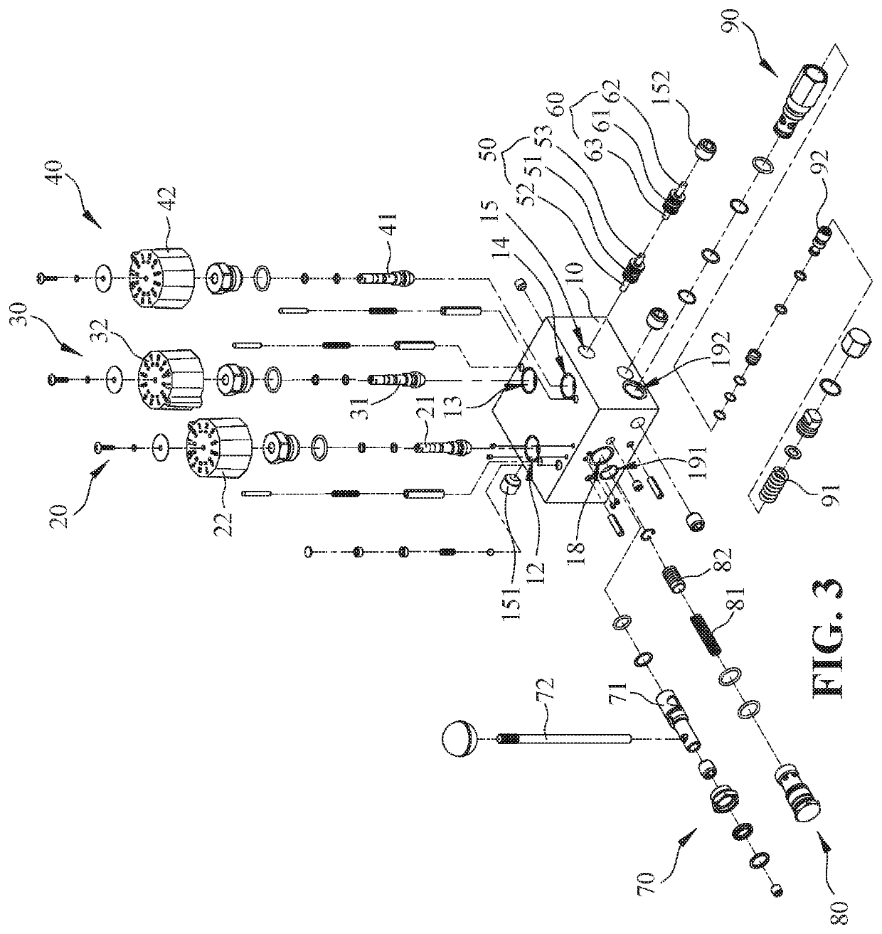
[0036]Referring to FIGS. 1-6, a liquid control valve assembly according to a first embodiment of the present invention includes a main casing 10, three valve bodies 20, 30, 40 and two plungers 50, 60. The main casing 10 has an external wall formed with an inlet 101 and three outlets 102, 103, 104. The main casing 10 defines a split-flow path 11, three valve chambers 12, 13, 14 and a balanced channel 15 therein such that the split-flow path 11 is in communication with the inlet 101 and the valve chambers 12, 13, 14 while the balanced channel 15 is in communication with the valve chambers 12, 13, 14 and the three outlets 102, 103, 104 so that when the inlet 101 is connected to a liquid...


PUM


Abstract

A liquid control valve assembly includes a main casing, three valve bodies and two plungers. The main casing has an external wall formed with an inlet and three outlets, defines a split-flow path, three valve chambers and a balanced channel therein such that the split-flow path is in communication with said inlet and said valve chambers while said balanced channel is in communication with said valve chambers and said three outlets. The valve bodies are disposed in the valve chambers respectively while the plungers are disposed in the balanced channel to move independently so that the liquid can be discharged stably from the outlets, thereby eliminating the problem of sudden rise and fall of the liquid flow and flow velocity of the liquid.

Description

CROSS-REFERENCE TO RELATED APPLICATION[0001]This application claims the priority of Taiwanese application No. 107145226, filed on Dec. 14, 2018, which is incorporated herewith by reference.BACKGROUND OF THE INVENTION1. Field of the Invention[0002]The present invention relates generally to a liquid control valve assembly, more particularly to a liquid control valve assembly having multiple outlets for balancing output liquid therefrom.2. The Prior Arts[0003]A conventional liquid control valve is a three-way valve that has one inlet end and two outlet ends, each of the two outlet ends is provided with a valve body in order to regulate the liquid flow and the flow velocity of the liquid flowing out from two outlet ends thereof.[0004]Since the conventional liquid control valve has only two outlet ends, only two external devices can be supplied with liquid and in the event there are three external devices that need liquid supply simultaneously, the user must install an additional control...

Claims


Application Information

Patent Timeline
IPC IPC(8): F16K11/085F16K31/60F16K11/16
CPCF16K31/602F16K11/161F16K11/0856F16K11/07F16K11/22F16K31/1245F16K31/061F16K31/0613F16K31/0627Y10T137/4365Y10T137/86107Y10T137/87249
Inventor TSOU, ERIC
Owner TSOU ERIC
Why Eureka
Try Eureka