Aerodynamic noise abatement device and method for air-cooled condensing systems

a technology of air-cooled condensing and noise abatement, which is applied in the direction of machines/engines, transportation and packaging, light and heating equipment, etc., can solve the problems of restricting the flow of exhaust steam, reducing the efficiency and output of turbines, and reducing the efficiency of turbines. , to achieve the effect of reducing aerodynamic resistan

Active Publication Date: 2005-03-03
BOMBARDIER RECREATIONAL PROD INC +1
View PDF24 Cites 23 Cited by
  • Summary
  • Abstract
  • Description
  • Claims
  • Application Information

AI Technical Summary

Benefits of technology

[0007] The present aerodynamic noise abatement device and method may be used to reduce the aerodynamic resistance presented by fluid pressure reduction device and more specifically, a noise abatement device is disclosed having at least one sparger with a cross-sectional profile that significantly reduces the fluid resistance and back- pressure within the turbine exhaust duct of an air-cooled condensing system that may be used in a power plant.
[0008] In accordance with another aspect of the present aerodynamic noise abatement device, an aerodynamic sparger is assembled from elliptically-shaped, stacked disks along a longitudinal axis that define flow passages connecting a plurality of inlets to the exterior outlets. The stacked disks create restrictive passageways to induce axial and lateral mixing of the fluid in staged pressure reductions that decrease fluid pressure and subsequently reduce the aerodynamic noise within the sparger.
[0010] In another embodiment, a method to substantially reduce aerodynamic resistance presented by a noise abatement device within the turbine exhaust duct of an air-cooled condenser is established.

Problems solved by technology

The spargers are restrictive devices that reduce fluid pressure by transferring and absorbing fluid energy contained in the bypass steam.
Because of space limitations within the duct, the spargers are generally spaced very closely and may impede the flow of exhaust steam from the steam turbine into the air-cooled condenser.
Conventional spargers used in modern power plants do not minimize the drag within the duct and subsequently can reduce the efficiency and output of turbine.
Applications with conventional spargers may not only limit turbine performance, but can also impact the expense and design of the air-cooled condenser.
Back-pressure restrictions introduced by the conventional spargers in the condenser circuit limit the total heat reduction the bypass steam that can be achieved thereby increasing the size and cost of the entire air-cooled condenser system.

Method used


Image

  • Aerodynamic noise abatement device and method for air-cooled condensing systems
  • Aerodynamic noise abatement device and method for air-cooled condensing systems
  • Aerodynamic noise abatement device and method for air-cooled condensing systems

Examples


Embodiment Construction

[0020] To fully appreciate the advantages of the present sparger and noise abatement device, it is necessary to have a basic understanding of the operating principles of a power plant and specifically, the operation of the closed water-steam circuit within the power plant. In power plants, recycling and conserving the boiler water significantly reduces the power plant's water consumption. This is particularly important since many municipalities located in arid climates require power plants to reduce water consumption.

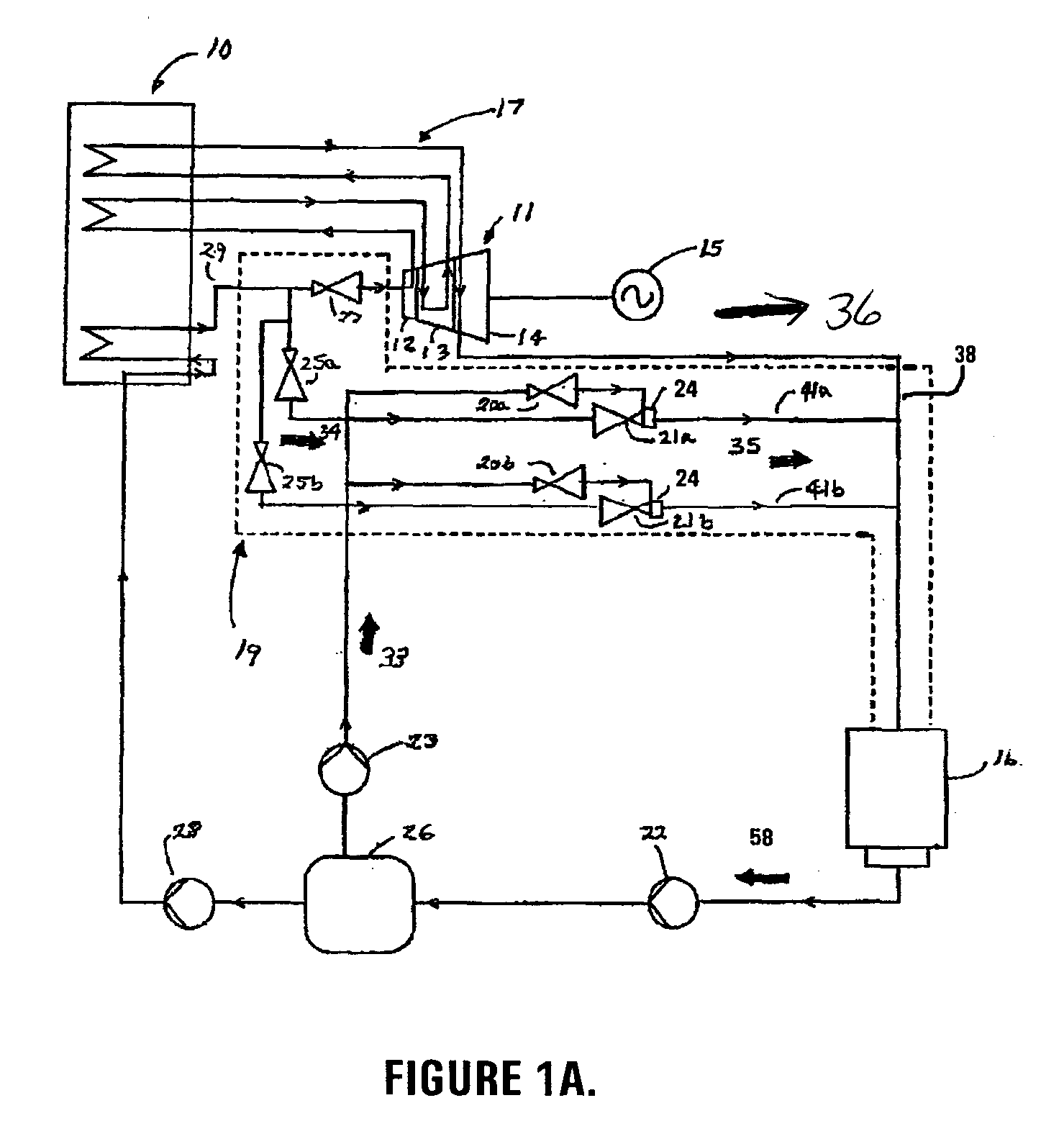
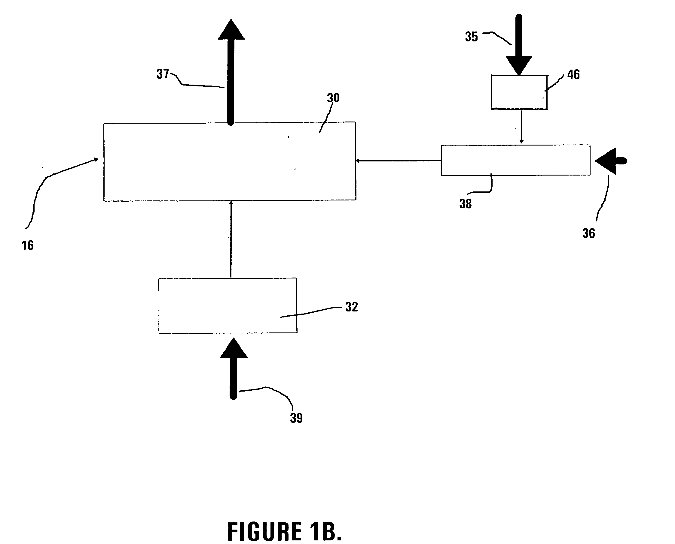
[0021] Turning to the drawings and referring initially to FIG. 1A, a block diagram of a steam turbine bypass circuit of a power plant is illustrated. The power generation process begins at the boiler 10. Energy conversion in the boiler 10 generates heat. The heat transforms the water pumped from a feedwater tank 26, using a feedwater pump 28, into steam. The feedwater tank 26 serves as a reservoir for the water-steam circuit. A series of steam lines or pipes 17 directs...


PUM


Abstract

The noise abatement device and method described herein makes known an apparatus and method for reducing the aerodynamic resistance presented by a fluid pressure reduction device in a large duct. More specifically, a noise abatement device is disclosed having at least one sparger with an aerodynamic profile that significantly reduces the fluid resistance within a turbine exhaust duct of an air-cooled condensing system that may be used in a power plant.

Description

TECHNICAL FIELD [0001] The noise abatement device and method described herein make known an apparatus and method for reducing the aerodynamic resistance presented by a fluid pressure reduction device in a duct. More specifically, a noise abatement device is disclosed having at least one sparger with an aerodynamic profile that significantly reduces the fluid resistance within a turbine exhaust duct of an air-cooled condensing system. BACKGROUND [0002] Modern power generating stations or power plants use steam turbines to generate power. In a conventional power plant, steam generated in a boiler is fed to a turbine where the steam expands as it turns the turbine to generate work to create electricity. Occasional maintenance and repair of the turbine system is required. When the turbine is taken out of service, it is typically more economical to continue boiler operation rather than shutting the boiler down during turbine repair. To accommodate this, the power plant is commonly design...

Claims


Application Information

Patent Timeline
Patent Type & Authority Applications(United States)
IPC IPC(8): B01F33/40F01D25/30F01K9/04F22G5/12
CPCB01F5/0453B01F5/0456F22G5/123F01D25/30F01K9/04B01F5/0465B01F25/3132B01F25/31322B01F25/313311
Inventor MCCARTY, MICHAEL W.
Owner BOMBARDIER RECREATIONAL PROD INC
Why Eureka
Try Eureka