Anti-cavitation valve assembly

a technology of anti-cavitation valves and assembly parts, which is applied in the direction of multiple way valves, mechanical equipment, transportation and packaging, etc., can solve the problems of forming literally thousands of minute bubbles, excessive noise and vibration of valves, and hearing loss of plant personnel, so as to reduce the pressure through the valve, eliminate cavitation and its attendant disadvantages, and minimize damage

Active Publication Date: 2005-08-04
CLA VAL
View PDF26 Cites 26 Cited by
  • Summary
  • Abstract
  • Description
  • Claims
  • Application Information

AI Technical Summary

Benefits of technology

[0009] The present invention resides in a valve assembly which reduces pressure through the valve while substantially eliminating cavitation and its attendant d...

Problems solved by technology

When subjected to high-pressure differentials or high flow rates, valves often exhibit excessive noise and vibration.
This can be loud enough to cause hearing loss in plant personnel if subjected to it for extended periods of time.
Cavitation occurs if the velocity of the fluid in the valve seating area becomes excessive, creating a sudden severe reduction in pressure that transforms the liquid into a vapor state, resulting in the formation of literally thousands of minute bubbles.
Should this occur in close proximity to any metal surface, damage can take place.
Over time, this can lead to valve failure due to the vibration and/or erosion.
Minimizing or eliminating these conditions that adversely effect operation and service life of the valve continues to be one of the most serious challenges encountered in the daily operation...

Method used


Image

  • Anti-cavitation valve assembly
  • Anti-cavitation valve assembly
  • Anti-cavitation valve assembly

Examples


Embodiment Construction

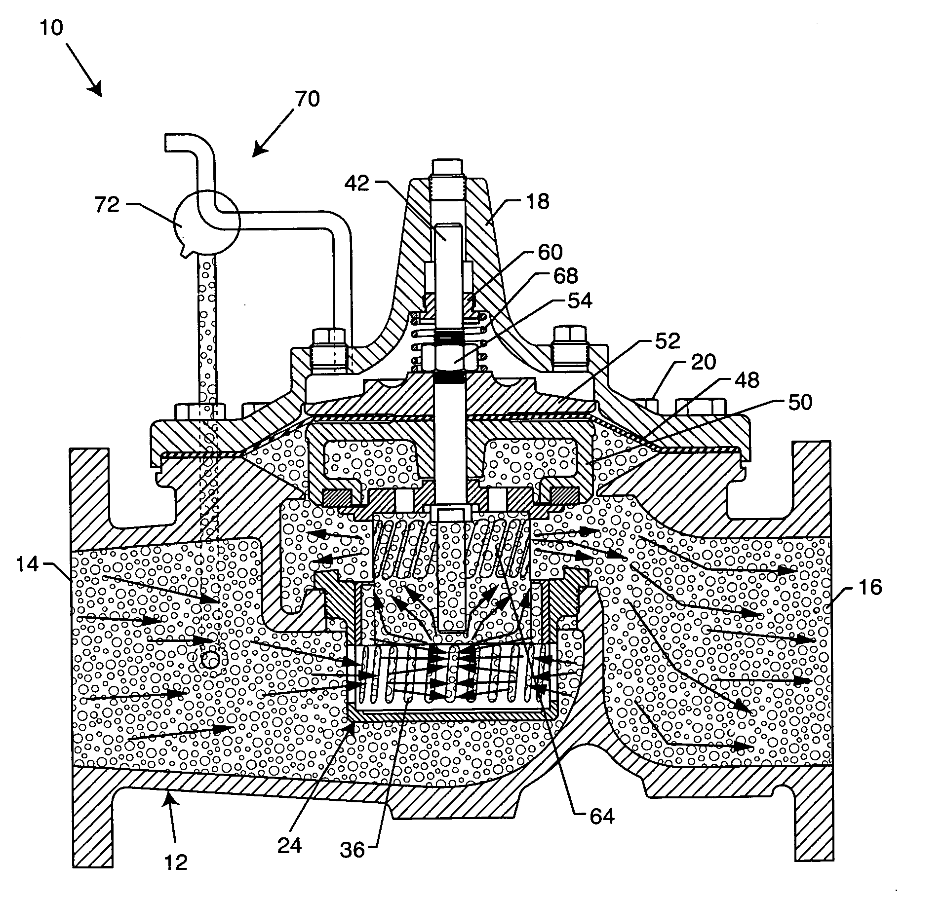
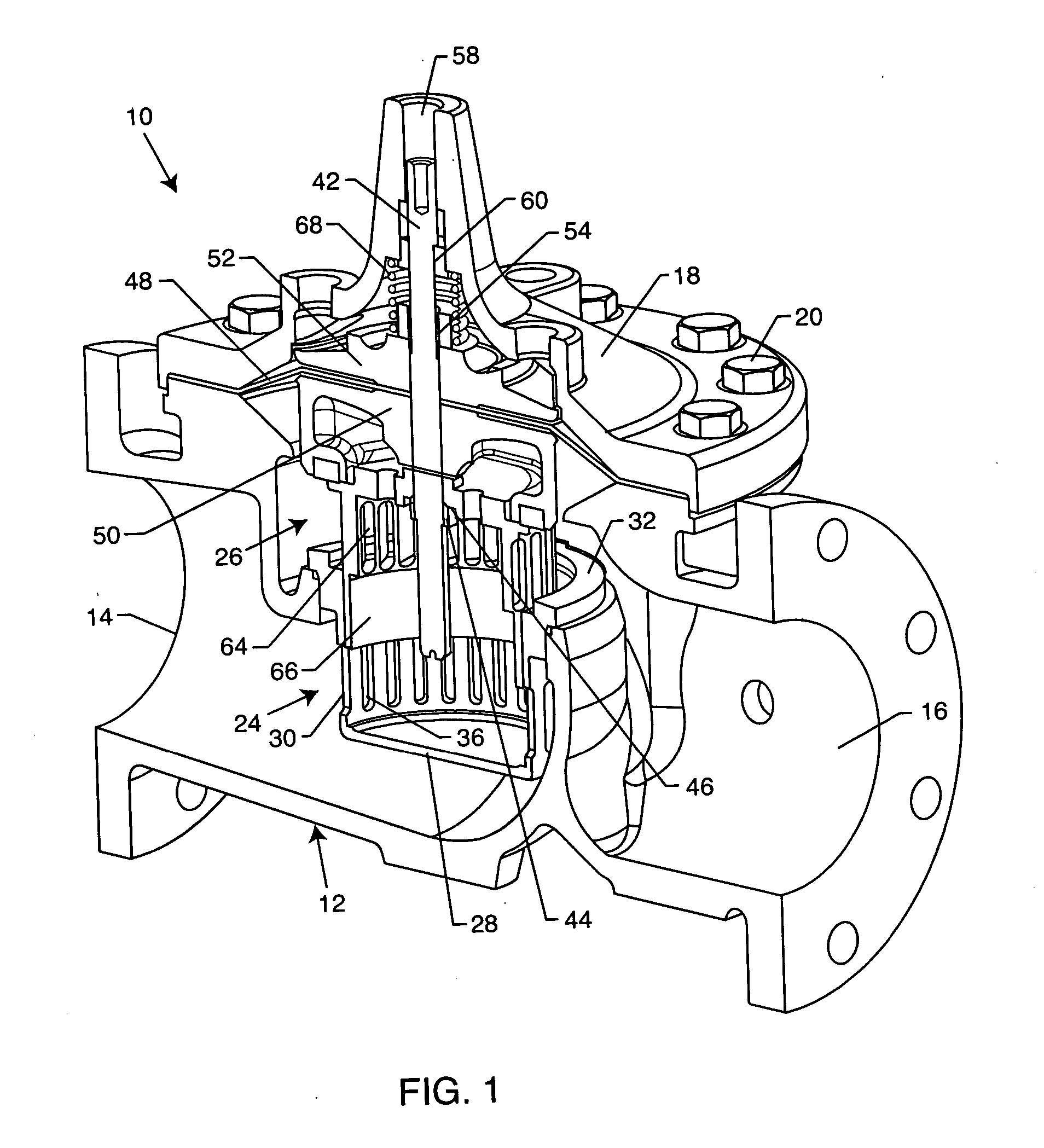
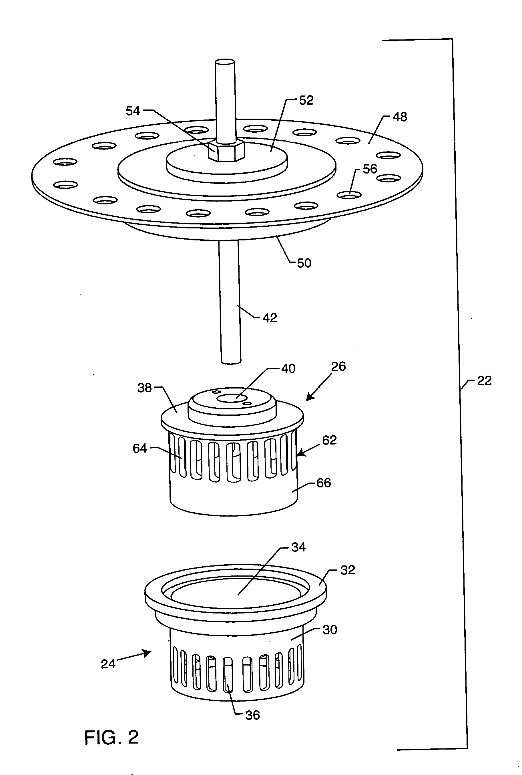
[0022] As shown in the accompanying drawings for purposes of illustration, the present invention resides in a valve assembly, generally referred to by the reference number 10. The assembly 10 of the present invention, as will be more fully described herein, is designed and configured to reduce fluid pressure through the valve assembly 10, while substantially eliminating cavitation. The valve assembly 10 of the present invention also directs the fluid in such a manner that erosion damage is minimized.

[0023] With reference now to FIG. 1, the valve assembly 10 includes a body or housing 12 defining a fluid inlet 14 and a fluid outlet 16. As illustrated, this fluid inlet 14 and outlet 16 are at generally opposite sides of the housing 12. A cover 18 is disposed on the housing 12 and attached or fixed into place using bolts 20 or the like. The housing 12 and cover 18 define the major pressure boundaries of the assembly 10, and collectively form an inner-fluid chamber between the inlet 14...


PUM


Abstract

A valve assembly for reducing cavitation includes a seat disposed within a valve housing intermediate a fluid inlet and outlet thereof. A disc guide is associated with the seat so as to be slidably moveable relative to the seat. The seat includes a wall defining an inner-chamber and having elongated slots formed therein so as to direct fluid towards a central portion of the fluid chamber. The disc guide includes a wall having elongated slots formed on an upper portion thereof, and a non-slotted lower portion configured to substantially occlude the elongated slots of the seat when the disc guide is moved into a closed position.

Description

RELATED APPLICATION [0001] This application claims the benefit of U.S. Provisional Application No. 60 / 542,111, filed Feb. 4, 2004.BACKGROUND OF THE INVENTION [0002] The present invention generally relates to control valves in high pressure fluid transfer systems. More particularly, the present invention relates to a control valve having anti-cavitation and low-noise properties. [0003] When subjected to high-pressure differentials or high flow rates, valves often exhibit excessive noise and vibration. This is usually attributable to the phenomenon of cavitation, which can range from relatively harmless levels called incipient cavitation to significantly more acute levels that actually damage valves and related piping. This can be loud enough to cause hearing loss in plant personnel if subjected to it for extended periods of time. Cavitation occurs if the velocity of the fluid in the valve seating area becomes excessive, creating a sudden severe reduction in pressure that transforms t...

Claims


Application Information

Patent Timeline
IPC IPC(8): F16K25/04F16K47/04F16K47/08
CPCF16K25/04F16K47/08F16K47/04Y10T137/86759Y10T137/86734
Inventor FOLK, ROBERTBECKER, DAVID
Owner CLA VAL
Why Eureka
Try Eureka