Flying device

A technology of flight equipment and equipment, which is applied in the direction of aircraft, offensive equipment, aircraft parts, etc., can solve problems such as ineffective effects, and achieve the effects of improving flexibility, improving flexibility, and reducing fluid resistance

Active Publication Date: 2011-01-12
朱晓义
View PDF6 Cites 21 Cited by
  • Summary
  • Abstract
  • Description
  • Claims
  • Application Information

AI Technical Summary

Problems solved by technology

At present, streamlined shells are mostly used to reduce fluid resistance, but the effect is not obvious

Method used


Image

  • Flying device
  • Flying device
  • Flying device

Examples


Embodiment 2

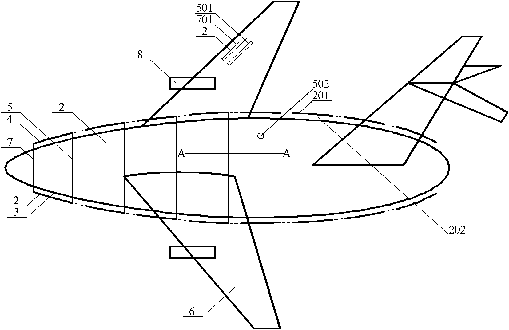
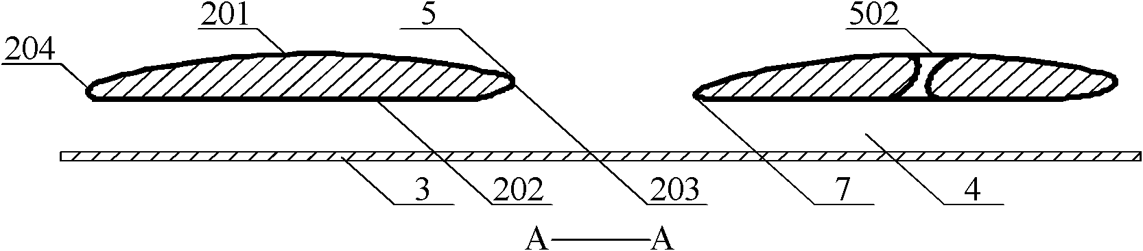
[0082] Such as Figure 1-3 As shown, different from Embodiment 1, a spoiler layer 601 formed by a plurality of spoilers is added on the upper surface of the wing 6, and an air passage 401 is formed between the upper surface of the wing 6, and the spoiler 2 The front side is a strip-shaped inlet 701, and the rear side is connected with a strip-shaped inlet 501. The outer surface 201 of the spoiler 2 is an arc surface, and the inner surface 202 is a plane. When the fluid passes through the spoiler layer 601, the fluid flows from the inlet 701 Introduced through the air channel 401 through the inner surface 202 of the plane and then exported from the outlet 501, after the fluid passes through the spoiler 2, the inner and outer surfaces of each spoiler 2 have a pressure difference due to different paths, so that the air channel 401 passes through the evenly distributed The inlet and outlet of the inlet and outlet, the high pressure area generated by the low flow rate in it is tran...

Embodiment 3

[0090] Such as Figure 4 Shown, different from embodiment 1 is that there is no wing, and engine 8 is located at left and right fuselage both sides, and empennage 602 is established at the rear to control direction.

[0091] After removing the wing, the volume of the aircraft is greatly reduced, and the resistance is also greatly reduced. A plurality of annular spoilers 2 surround the upper half of the fuselage, because the surface area formed by the inner and outer layers of the upper half of the fuselage by the plurality of spoilers is greater than The lift generated by traditional wings is no less than that of ordinary airplanes. More importantly, the pressure and friction generated by the fluid resistance that wraps tightly around the fuselage like a python is greatly reduced, which improves the speed of the aircraft and saves energy. A plurality of spoilers 2 may also be arranged on the upper surface of the empennage 602 .

Embodiment 4

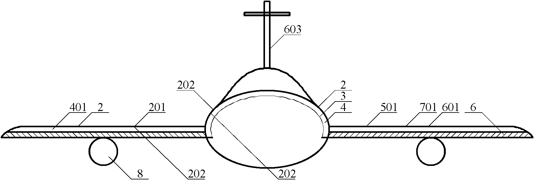
[0093] Such as Figure 5 As shown, different from Embodiment 3, front wings 603 are arranged on both sides of the front end to form a canard layout, but the front and rear wings are smaller than traditional aircraft. On the left and right sides or bottom of the lower half (not pictured).

[0094] The fuselage and wings of the aircraft generate lift at the same time, which greatly increases the lift of the aircraft, increases the carrying capacity, reduces fluid resistance, reduces energy consumption, and increases the flight radius. When the flight angle of attack is 60°-70°, multiple Spoiler 2 forms inner and outer two layers of fluid layers to infiltrate each other, and there will be no danger of fluid breaking away from the fuselage like a smooth surface, thereby improving the flexibility and combat effectiveness of the aircraft.

[0095] Another embodiment, different from the above, is that the spoiler 2 surrounds the fuselage.

[0096] Another embodiment, different from...


PUM


Abstract

The invention discloses a flying device which comprises a device main body, a sealed inner shell located on the device main body and an outer shell located outside the inner shell. An air channel is arranged between the inner shell and the outer shell; the outer shell located on the upper part of the device main body comprises a plurality of spoilers, and a guide inlet and a guide outlet which are communicated with the outside are arranged between every two spoilers or on each spoiler per se. The air channel is communicated with the guide inlet and the guide outlet respectively; the surface path passed by fluid on the external surfaces of the spoilers is longer than the air path in the air channel on internal surfaces of the spoilers in a corresponding zone, therefore, a high pressure zone produced by low flow rate in the air channel is transferred to a low pressure zone produced by high flow rate outside the outer shell from the guide outlet; and the surface path passed by fluid on the outer shell part at the upper part of the wing is longer than the surface path of the outer shell part at the lower part of the wing in the flying direction. The invention can increase the speed ofthe flying device and can save energy.

Description

technical field [0001] The present invention relates to a maneuvering device, in particular to a flight device that generates a greater source of lift and is more energy-efficient. Background technique [0002] It has been more than 100 years since the appearance of the aircraft. Due to the different paths and flow velocities of the upper and lower surfaces of the wing, the pressure difference is generated, thereby generating lift. The wing has been the only source of lift for a hundred years. There is nothing wrong with it in theory and practice. Variety. [0003] When the prior art aircraft travels fast, it is unavoidably surrounded by thick fluid around it. Since the length of the aircraft is relatively long relative to its diameter, the pressure of the fluid inwardly wraps around tightly and flows from the beginning to the end, causing a great deal of pressure. Friction, the faster the speed, the greater the pressure, the greater the friction, and the greater the fluid ...

Claims


Application Information

Patent Timeline
Patent Type & Authority Applications(China)
IPC IPC(8): B64C1/38B64C3/36B64C3/58B64C39/06F42B10/62F42B10/64
Inventor 朱晓义
Owner 朱晓义
Why Eureka
Try Eureka