
User interface with proximity detection for object tracking

a user interface and object tracking technology, applied in the field of user interfaces with proximity detection for object tracking, can solve the problems of reducing the reliability of switches, affecting the use of sensors, so as to facilitate the placement of sensing layers, increase the sensitivity threshold of touch pads, and facilitate the effect of placing touch pads

Active Publication Date: 2022-01-04
UUSI
View PDF101 Cites 0 Cited by
  • Summary
  • Abstract
  • Description
  • Claims
  • Application Information

AI Technical Summary

Benefits of technology

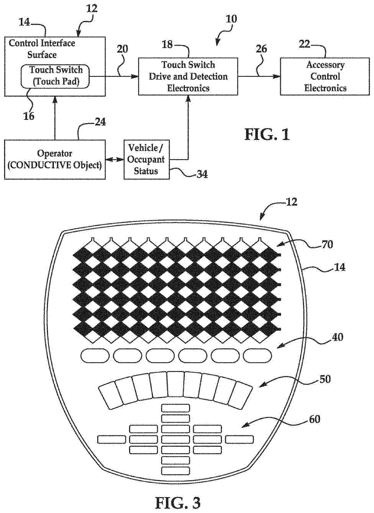
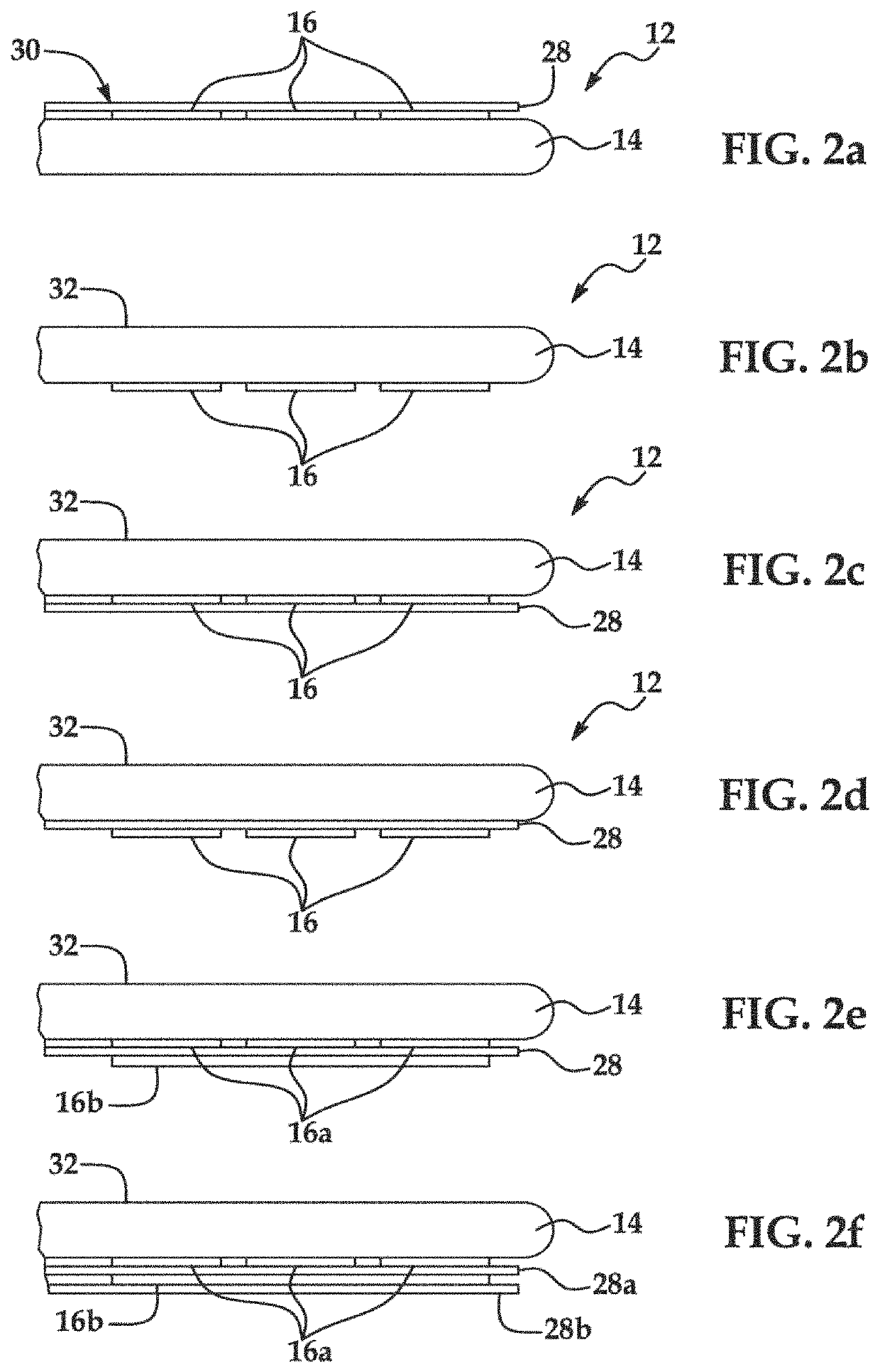
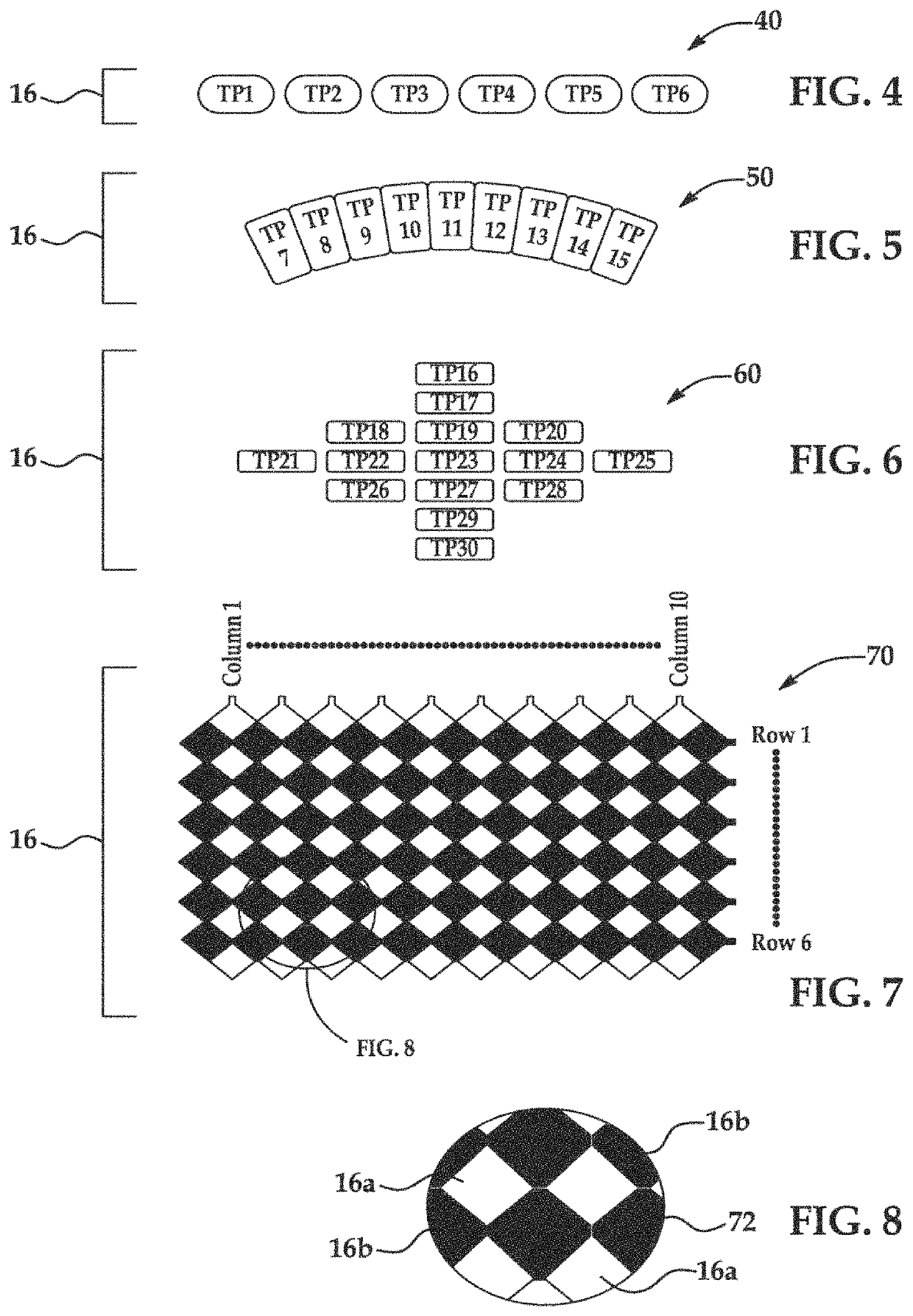
The present patent is about a user interface device with a touch pad that can be mounted behind non-conductive materials like glass or plastic. The device uses mutual capacitance detection to enable single point and multipoint sensing of human touch through thick surfaces. The touch pad can be integrated with a display device to create visual feedback and can be tailored to follow the contours of the surface. The device also facilitates sharing of electrical interface hardware and input controls for multiple vehicle accessories and personal electronic accessories. Additionally, a camera power system is described that includes a rechargeable battery that is charged by a combination of the vehicle electrical system and a solar cell attached to the camera assembly. This allows for extended battery life and reduces the cost and space required for the camera.

Problems solved by technology

As a result, mechanical switches may exhibit reduced performance over time as activation causes wear on moving components and electrical contacts.
Switch reliability declines and contacts may become intermittent with continued use.
In addition, repeated physical contact may lead to deterioration of switch face legends and graphics.
Mechanical switches are also susceptible to contamination from external matter like dirt, food, and liquids.
Ultimately, mechanical switches are expensive for automotive use.
In addition to inherent physical limitations and cost, mechanical switches present constraints to automotive ergonomics and aesthetics by limiting vehicle styling and layout options.
In particular, mechanical switches are permanently fixed, numerous, and occupy relatively large portions of the surface of the user interface.
As vehicle accessories are augmented with additional features, the user interface used to control these accessories becomes increasingly complex.
Together, the mechanical switches and the displays of a control interface consume valuable space of the surface of the control interface and increase overall cost.
Excessive buttons or knobs clutter the interface and may result in the operator hunting for a desired switch.
Sophisticated multi-function control knobs, those with switches that activate by tilting, pivoting, or swiveling, may have obscure functions and may be difficult to maneuver for some operators.
Furthermore, sophisticated control knobs have many intricate parts making them expensive and prone to failure.

Method used


Image

  • User interface with proximity detection for object tracking
  • User interface with proximity detection for object tracking
  • User interface with proximity detection for object tracking

Examples


Embodiment Construction

[0041]As those of ordinary skill in the art will understand, various features illustrated and described with reference to any one of the Figures may be combined with features illustrated in one or more other Figures to produce embodiments that are not necessarily explicitly illustrated or described. Likewise, those of ordinary skill in the art will recognize that embodiments illustrated in particular Figures may be used in applications described with respect to embodiments illustrated in other Figures. The combinations of features illustrated provide representative embodiments for representative applications. However, various combinations and modifications of the features consistent with the teachings of this disclosure may be desired for particular applications or implementations.

[0042]Touch sensitive user interface devices according to the present disclosure may be used to advantage in a wide variety of applications. In vehicle applications, for example, touch sensitive user inter...


PUM


Abstract

A system or method for tracking items proximate a user interface device include a user interface device having at least one solid-state touch-sensitive region and a receiver for wirelessly receiving a signal from at least one item to determine proximity of the item relative to the user interface device. The device may also include a display screen for displaying controls and information. The user interface device may be permanently or removably mounted in a vehicle and used to interface with vehicle systems and personal electronic devices. Tracked items or objects may include passive or active data tags and communicate identification information and optionally position information. The device may alert the user to movement of tracked objects, and / or confirm presence of a group of objects. The device may use various wired or wireless devices to control selections and / or a cursor on the display.

Description

CROSS-REFERENCE TO RELATED APPLICATION(S)[0001]The present application is a continuation of U.S. Ser. No. 14 / 028,941, filed Sep. 17, 2013, which is a continuation-in-part of U.S. Ser. No. 12 / 496,938, filed Jul. 2, 2009 (now U.S. Pat. No. 9,046,967, issued Jun. 2, 2015), the entire disclosures of which are hereby expressly incorporated by reference.TECHNICAL FIELD[0002]The present disclosure relates to systems and methods for detecting proximity of one or more objects relative to a user interface.DESCRIPTION OF THE RELATED ART[0003]A vehicle, such as an automobile, truck, boat, and the like typically includes one or more user interfaces accessible by occupants including an operator and / or passengers for displaying information and providing input for various accessories located in and / or around the vehicle. A user interface may include one or more controls that an occupant uses to control an accessory, in addition to a display for displaying status information for the vehicle and / or a...

Claims


Application Information

Patent Timeline
Patent Type & Authority Patents(United States)
IPC IPC(8): G06F3/0488G06F3/0354B60K35/00B60K37/06G06F3/041G06F3/044B60K35/10
CPCG06F3/0488B60K35/00B60K37/06G06F3/03547G06F3/0446G06F3/04166G06F3/04883G06F3/04886B60K2370/569G06F2203/04101B60K35/10B60K35/80B60K2360/569B60K35/26B60K35/22
Inventor WASHELESKI, JOHN M.SHANK, DAVID W.
Owner UUSI
Learn More