Speaker device and area reproduction apparatus
a technology of area reproduction and speaker device, which is applied in the direction of transducer details, electrical transducers, electrical apparatus, etc., can solve the problems of not being able to achieve sufficient horizontal reproduction performance, and not being able to prevent unnecessary sound reflection, so as to enhance sound reproduction performance and prevent unnecessary sound reflection
- Summary
- Abstract
- Description
- Claims
- Application Information
AI Technical Summary
Benefits of technology
Problems solved by technology
Method used
Image

Examples
first embodiment
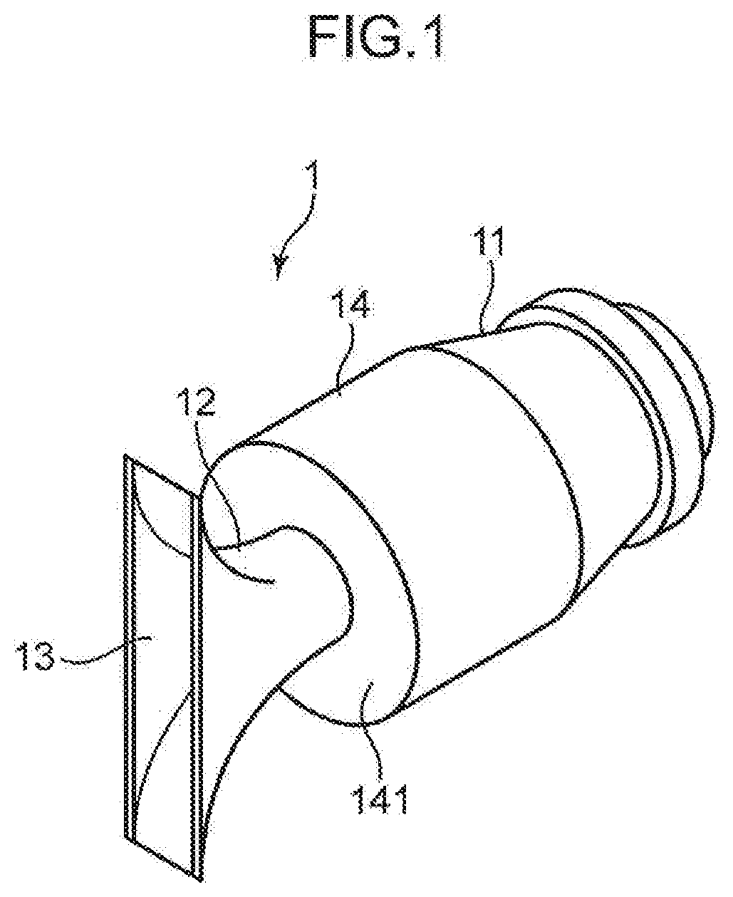
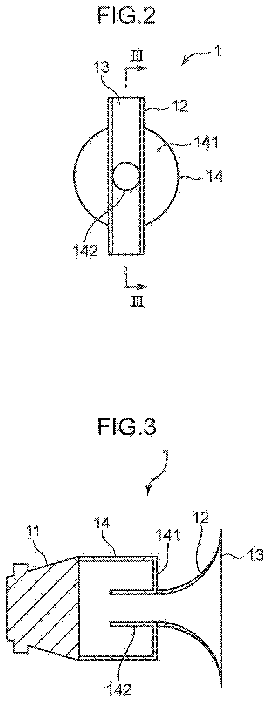
[0053]FIG. 1 is a perspective view of an appearance of a speaker device according to a first embodiment of the present disclosure. FIG. 2 is a front view of the speaker device illustrated in FIG. 1. FIG. 3 is a cross-sectional view of the speaker device illustrated in FIG. 2, taken along a line III-III.
[0054]A speaker device 1 illustrated in FIGS. 1, 2, and 3 includes a speaker 11, a horn 12, a slit opening 13, and a connecting part 14.
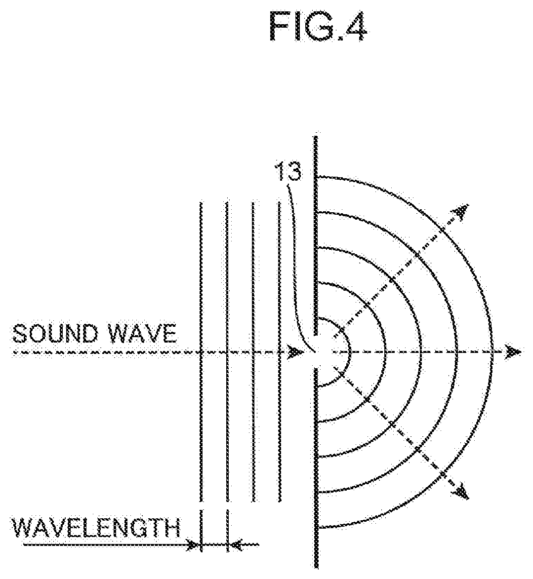
[0055]The speaker 11 outputs sound. The horn 12 emits sound output from the speaker 11. The slit opening 13 is formed on a front surface of the horn 12. The slit opening 13 has a rectangular shape whose vertical side is longer than a horizontal side. An outer edge of the slit opening 13 matches an outer edge of the front surface of the horn 12.
[0056]The connecting part 14 connects the speaker 11 and the horn 12, and has a space inside. The connecting part 14 removes sound in a predetermined frequency band from the sound output from the speaker 11. The...
second embodiment
[0093]FIG. 13 is a perspective view of an appearance of a speaker device according to a second embodiment of the present disclosure. FIG. 14 is a front view of the speaker device illustrated in FIG. 13. FIG. 15 is a cross-sectional view of the speaker device illustrated in FIG. 14, taken along a line XV-XV.
[0094]A speaker device 1A illustrated in FIGS. 13,14, and 15 includes a speaker 11, a horn 12, a slit opening 13, and a connecting part 14A. Note that in the second embodiment, the same components as those of the speaker device 1 according to the first embodiment are denoted by the same reference numerals, and a description thereof will be omitted.
[0095]The connecting part 14A connects the speaker 11 and the horn 12, and has a space inside. The connecting part 14A removes sound in a predetermined frequency band from sound output from the speaker 11. The connecting part 14A includes a front panel 141 and a sound conduit 142. The front panel 141 is provided in a sound output directi...
third embodiment
[0103]FIG. 17 is a perspective view of an appearance of a speaker device according to a third embodiment of the present disclosure. FIG. 18 is a front view of the speaker device illustrated in FIG. 17. FIG. 19 is a cross sectional view of the speaker device illustrated in FIG. 18, taken along a line XIX-XIX.
[0104]A speaker device 1B illustrated in FIGS. 17, 18 and 19 includes a speaker 11, a horn 12B, a slit opening 13, and a connecting part 14. Note that in the third embodiment, the same components as those of the speaker device 1 according to the first embodiment are denoted by the same reference numerals, and a description thereof will be omitted.
[0105]The horn 12B includes a folding part 122 that reflects sound in a direction opposite to a sound output direction and a reflecting part 123 that reflects sound reflected by the folding part 122 again in the output direction. The reflecting part 123 is a part of a front panel 141 of the connecting part 14, the part being covered with...
PUM
 Abstract
Description
Claims
Application Information
 - R&D Engineer
- R&D Manager
- IP Professional
- Industry Leading Data Capabilities
- Powerful AI technology
- Patent DNA Extraction
Browse by: Latest US Patents, China's latest patents, Technical Efficacy Thesaurus, Application Domain, Technology Topic.
© 2024 PatSnap. All rights reserved.Legal|Privacy policy|Modern Slavery Act Transparency Statement|Sitemap