Resin-based male chastity device utilizing Anti-pullouts and multiple overmolded synthetic regions and coverings

Inactive Publication Date: 2020-08-27
MADORE AUSTIN
View PDF0 Cites 2 Cited by
  • Summary
  • Abstract
  • Description
  • Claims
  • Application Information

AI Technical Summary

Problems solved by technology

Modern devices range from simple leather or plastic toys commonly sold by adult stores to expensive high-security stainless steel devices.
Some designs have a curved or angled tube to make ere

Method used


Image

  • Resin-based male chastity device utilizing Anti-pullouts and multiple overmolded synthetic regions and coverings
  • Resin-based male chastity device utilizing Anti-pullouts and multiple overmolded synthetic regions and coverings
  • Resin-based male chastity device utilizing Anti-pullouts and multiple overmolded synthetic regions and coverings

Examples


Embodiment Construction

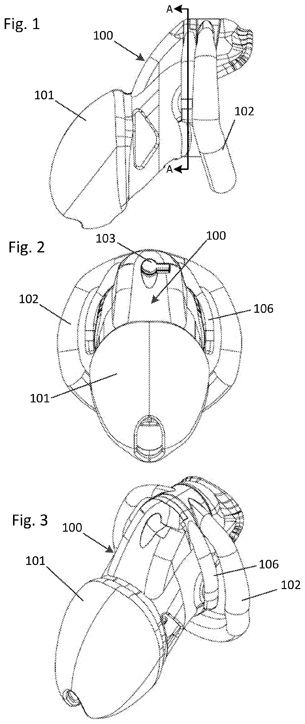
[0020]Turning now to FIGS. 1 through 3, a first embodiment of the present invention is a flexible male chastity device 100 comprised of a ventilated cage housing comprising shaft portion 101 with base portion 102 configured to encase the shaft and head of the penis. Base portion 102 is generally circular, or horizontally oval when viewed from the rear, and is constructed of resin or hard plastic. Those having skill in the art will recognize that some, or all, of base portion 102 may be covered, or overmolded, with silastic or some other flexible, inert silicone elastomer such as rubber. Shaft portion 101 and base portion 102 are worn such that the penis resides in shaft portion 101 and base portion 102 is insinuated behind the scrotum. Since base portion 102 is constructed of resin or hard plastic, base portion 102 is placed behind the scrotum by stretching and pulling the scrotum to go through the central lumen of base portion 102. This secures this first embodiment of the present ...


PUM


Abstract

A flexible male chastity device that may be permanently affixed to the scrotum and penis of the user and is substantially non-removable is disclosed. This device also includes a hinged insert or anti-pullout ring. Also, this device is constructed from ridged and flexible materials and includes multiple regions of overmolded synthetic coverings.

Description

CROSS-REFERENCE TO RELATED APPLICATIONS[0001]This application takes benefit of U.S. Prov. App. No. 62 / 827,016 filed Mar. 30, 2019 and U.S. Prov. App. No. 62 / 776,923 filed Dec. 7, 2018 and incorporates both of these in their entirety by reference.FIELD OF THE INVENTION[0002]A flexible male chastity device that may be permanently affixed to the scrotum and penis of the user and is substantially non-removable is disclosed. This device also includes a hinged insert or anti-pullout ring. Also, this device is constructed from ridged and flexible materials and includes multiple regions of overmolded synthetic coverings.BACKGROUND OF THE INVENTION[0003]The invention relates to a flexibly constructed male chastity device for protracted wear on the male sex organ to prevent sexual intercourse and masturbation.[0004]In the prior art, a chastity belt is a locking item of clothing designed to prevent sexual intercourse and masturbation as well as to protect the wearer from sexual temptation. Cha...

Claims


Application Information

Patent Timeline
IPC IPC(8): A61F5/00
CPCA61F5/0096A61F5/37A61F6/02
Inventor MADORE, AUSTIN
Owner MADORE AUSTIN
Why Eureka
Try Eureka