Supercharge Your Innovation With Domain-Expert AI Agents!

Saddle stirrup adjustable strap d-ring

a technology of adjustable straps and saddles, which is applied in the direction of saddles, stirrups, applications, etc., can solve the problems of limited knee flexibility, difficult removal or replacement of stirrups of western saddles, and inability to allow the rider to easily stand in the stirrups, etc., to achieve greater safety, stability, and control of the rider

Active Publication Date: 2020-09-10
SPORTS SADDLE INC
View PDF0 Cites 0 Cited by
  • Summary
  • Abstract
  • Description
  • Claims
  • Application Information

AI Technical Summary

Benefits of technology

The patent text describes a modified saddle D-ring and a saddle that uses the D-ring to support a stirrup strap. The D-ring has a loop of varying radius, with a curved bottom portion and two contiguous upper surface sections that abut the strap. The D-ring also has elongated curved loop that allows limited pivotal forward movement of the stirrup with respect to the saddle. The D-ring strap positioning members (called "T" shaped projections) extend upward from the D-ring to adjust and hold it in place. The "technical effect" of the invention is to provide added comfort and safety to the horse, as well as greater stability and control for the rider.

Problems solved by technology

The normal setting places approximately 60% of the rider's weight toward the rear and moves the weight of the rider toward the rear when they exert pressure on the stirrups providing a more secure seat position but doesn't allow the rider to easily stand in the stirrups.
Moreover, the stirrup of western saddle is difficult to remove or replace and the same stirrups usually are kept on for the life of the saddle.
As an example some pleasure riders may have limited knee flexibility making it difficult for them to use the stirrup to mount the horse and / or use the stirrups while riding.
Riders with leg problems can no longer flex their knees properly for the appropriate upright riding stance.

Method used


Image

  • Saddle stirrup adjustable strap d-ring
  • Saddle stirrup adjustable strap d-ring
  • Saddle stirrup adjustable strap d-ring

Examples


Embodiment Construction

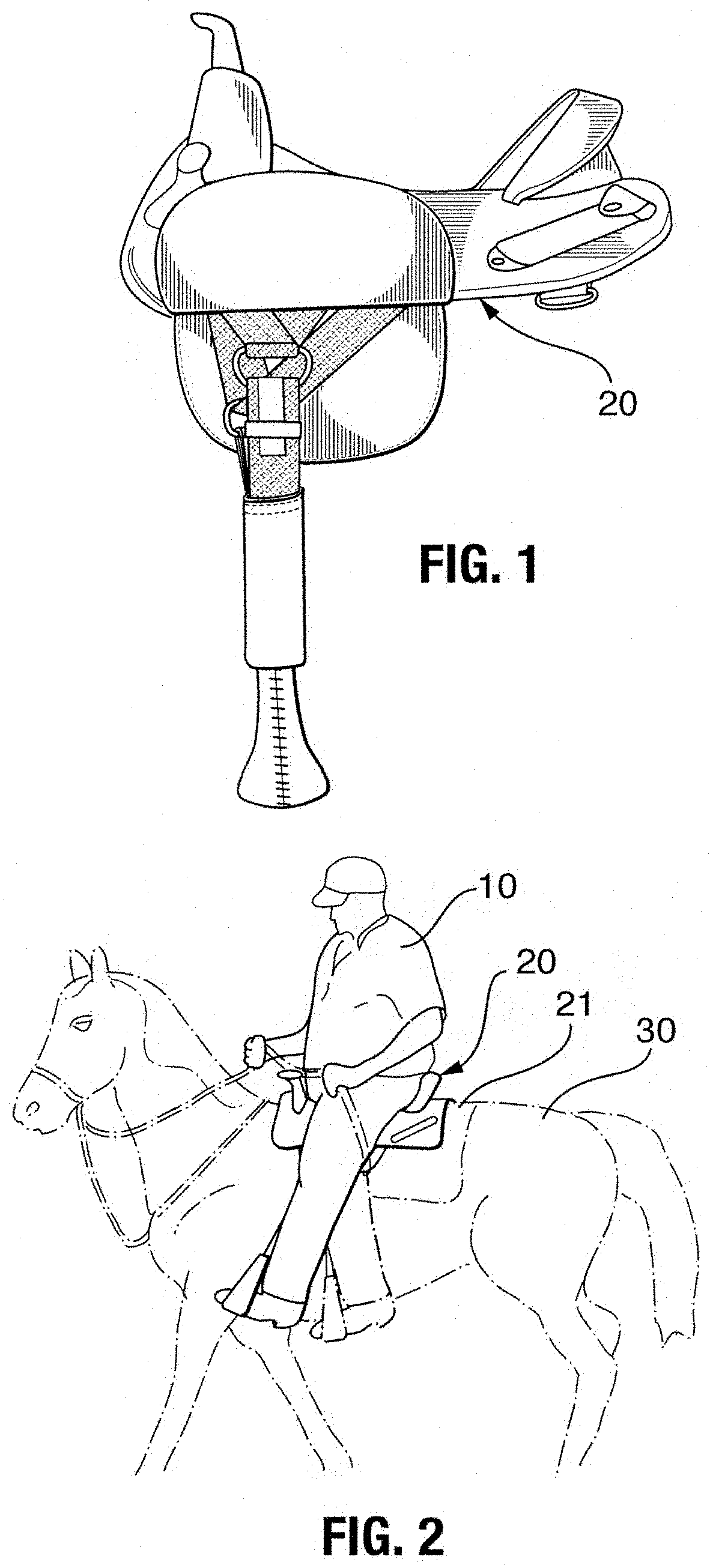
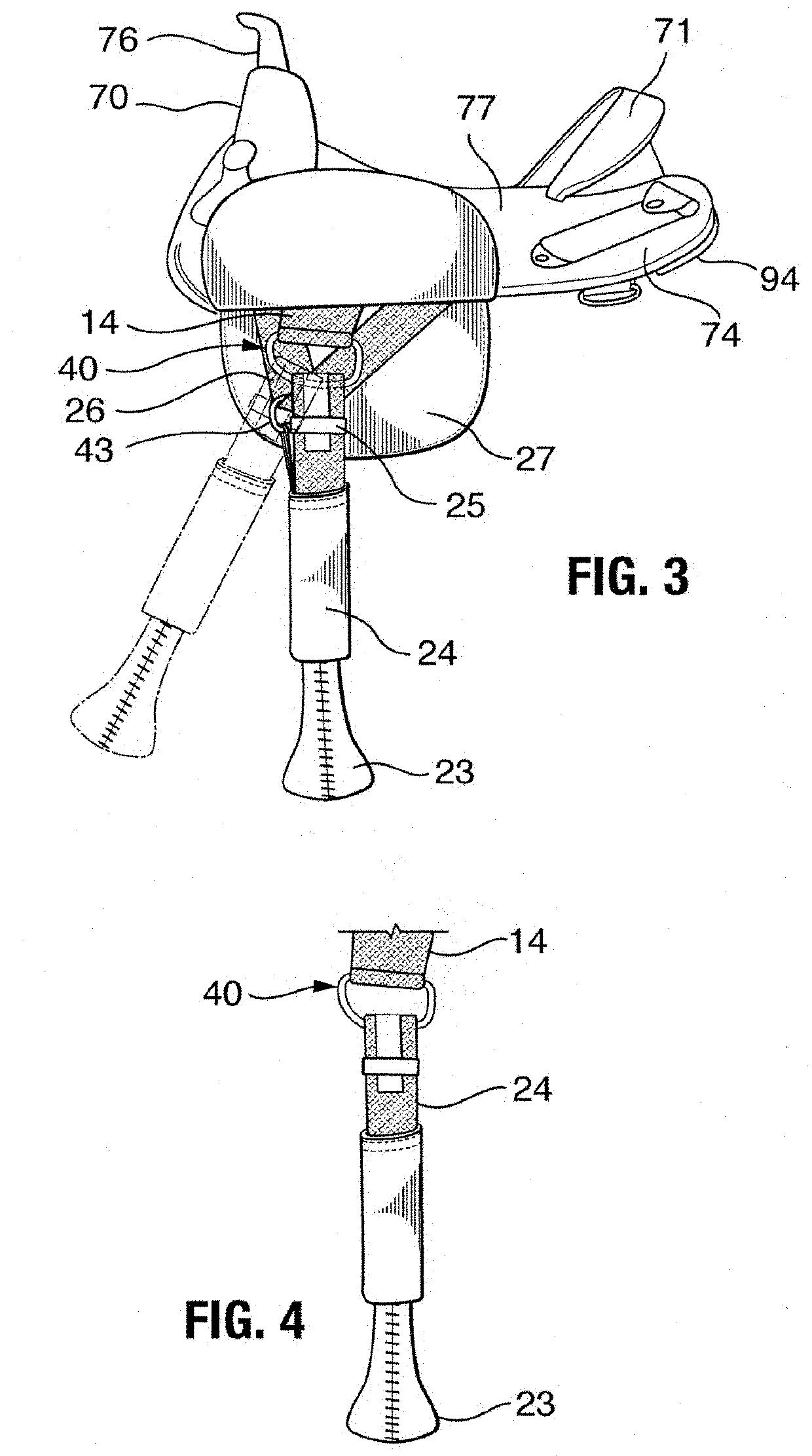
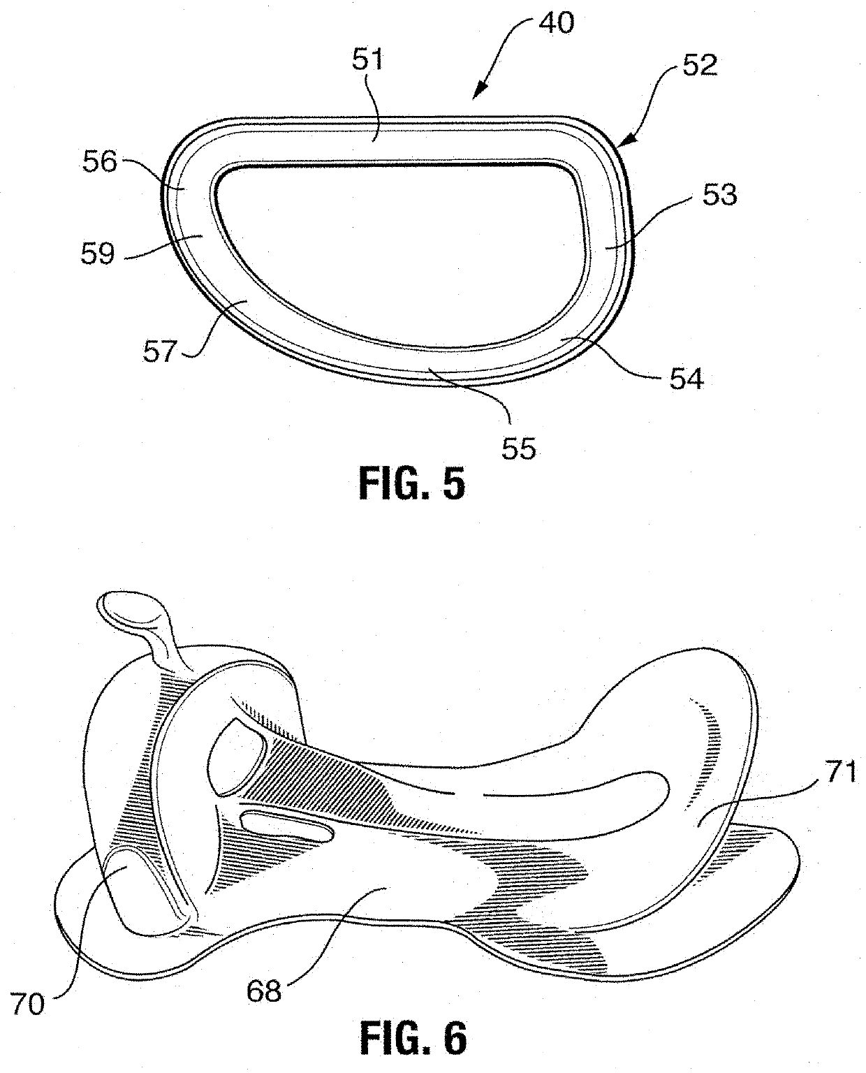
[0033]Illustrated in FIG. 1, is a rider 10 sitting on a saddle 20 mounted on the back of a horse 30. The saddle 20 as shown in the drawings is a western style saddle and more particularly known by Applicants' tradename as a TREELESS saddle in that the saddle tree comprises a two piece independent bar less system as described in U.S. Pat. Nos. 5,187,924 and 5,018,340 hereby incorporated by reference in its entirety. Conventional English and western saddles utilize a tree have a pair of longitudinal members such as a pair of bars 68 connect the pommel 70 which may support a saddle horn 76, and the cantle 71. The pommel 70 and the cantle 71 are made of solid material such as wood, fibreglass, or combinations thereof. The flexible tree or TREELESS saddle shown in FIGS. 1-3 only uses the cantle and pommel parts of the tree flexibly connected together. The independent pommel / cantle two-piece system or TREELESS saddle lets the horse flex and move freely while letting the rider keep complet...


PUM


Abstract

A modified saddle D-ring having a loop of a varying radius for supporting a stirrup strap on a saddle. The stirrup supporting strap is looped around a lower span portion of the D-ring which has an upper span portion anchored to the saddle. The lower span has an upper surface that abuts against the saddle supporting strap and such upper surface includes first and second contiguous portions disposed at a preselected angle to one another with the length being greater than the width of the stirrup supporting strap. The D-ring includes an elongated curved loop extending forward at a varying radius depicting a parabolic curve. The elongated D-ring allows limited pivotal forward movement of the stirrup with respect to the saddle. One or more “T” shaped projections may extend upward from one a selected position at the bottom of the D-ring for adjusting and holding the D-ring in position.

Description

FIELD OF INVENTION[0001]The present invention relates generally to riding saddles and more particularly to a modified elongated D-ring with a loop having a front portion of varying radi for providing limited pivotal movement of the stirrup and stirrup strap with respect to the saddle.BACKGROUND OF INVENTION[0002]A conventional western type saddle includes a framework or tree defining the shape of the saddle whereby the typical saddle tree is ridged and consists of spaced apart parallel bars connecting a horn, pommel and cantle with the seat disposed there between resting upon the bars. The tree is composed of wood, metal, plastic, fibreglass, synthetic material or combinations thereof. * The tree is usually covered with leather on all visible parts of the saddle. Trees differ in width of the gullet and bars, pitch of the bars (steep to flat), and length of the bars. The tree also influence the shape of the pommel and cantle on the seat on the saddle. The bars form the primary loadin...

Claims


Application Information

Patent Timeline
Patent Type & Authority Applications(United States)
IPC IPC(8): B68C3/02
CPCB68C2003/0008B68C3/02B68C1/16
Inventor MARSHALL, M. DIANNE
Owner SPORTS SADDLE INC
Features
  • R&D
  • Intellectual Property
  • Life Sciences
  • Materials
  • Tech Scout
  • Unparalleled Data Quality
  • Higher Quality Content
  • 60% Fewer Hallucinations
Learn More