Management device, and identification method and recording medium storing program
a management device and recording medium technology, applied in the field of management devices and the like, can solve problems such as difficulty in finding the state of optical transmission systems
- Summary
- Abstract
- Description
- Claims
- Application Information
AI Technical Summary
Benefits of technology
Problems solved by technology
Method used
Image


Examples
second example embodiment
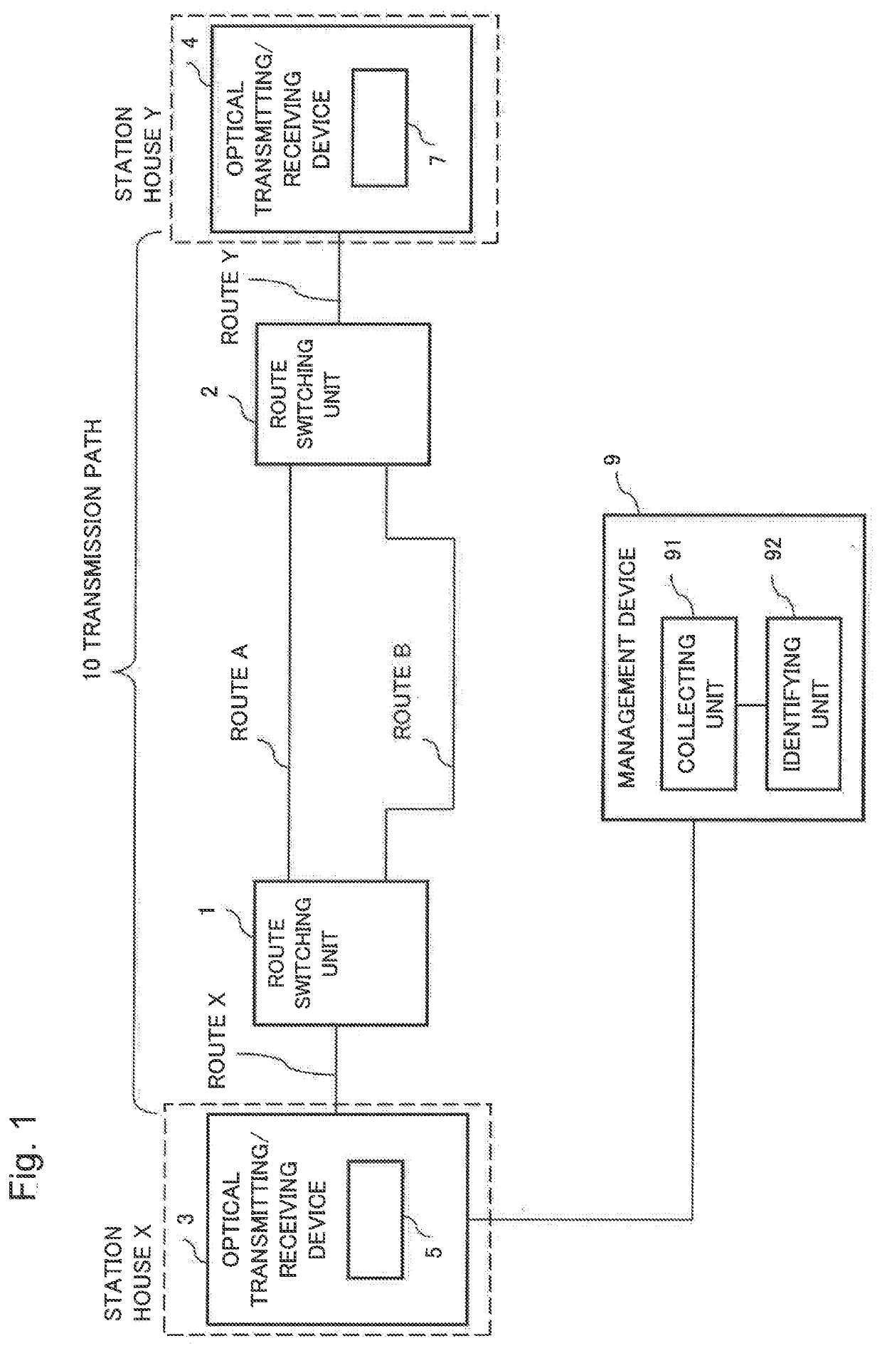
[0059]Next, an optical transmission system and a management device according to a second example embodiment are described. The second example embodiment is an example in which optical transmitting / receiving devices 3 and 4 of the optical transmission system include a plurality of optical transponders, and a management device 9 collects transmission delay times in respective transmission paths from the plurality of optical transponders of the optical transmitting / receiving device 3, and identifies transmission routes of the transmission paths.
[0060]FIG. 6 is a block diagram illustrating configurations of the management device and the optical transmission system according to the second example embodiment. Hereinafter, in the second example embodiment, points different from those in the first example embodiment are described in detail, the same configurations as those in the first example embodiment are indicated with the same reference signs, and a detailed description thereof is thus...
modification example of second example embodiment
[0069]Although each optical transponder 5 on a station house X side measures a transmission delay time of the transmission path 10 in the example indicated in the second example embodiment described above, the disclosed subject matter is not limited thereto. For example, each optical transponder 7 on a station house Y side may also be provided with a function of measuring the transmission delay time of the transmission path 10. In this case, the collecting unit 91 of the management device 9 collects the transmission delay time measured by each optical transponder 7.
Advantageous Effects of Second Example Embodiment
[0070]According to the management device in the second example embodiment, a transmission route of a transmission path may be identified, even when communication with equipment disposed on the transmission path of an optical transmission system is not possible. This is because, on the basis of route delay information indicating a relation between a transmission route and a ...
third example embodiment
[0072]Next, a management device and an optical transmission system according to a third example embodiment are described. The third example embodiment is an example in which a function adding unit is added onto the transmission path 10 of the optical transmission system according to the second example embodiment.
[0073]FIG. 8 is a block diagram illustrating configurations of the management device and the optical transmission system according to the third example embodiment. As illustrated in FIG. 8, the optical transmission system according to the third example embodiment has a configuration in which a function adding unit 31 and a function adding unit 32 are added onto the routes A and B of the transmission path 10 according to the second example embodiment, respectively.
[0074]For example, it is assumed that the function adding unit 31 and the function adding unit 32 are optical add-drop multiplexers (OADMs) having different add / drop branching ratios. In the optical transmission sys...
PUM
 Abstract
Description
Claims
Application Information
 - R&D
- Intellectual Property
- Life Sciences
- Materials
- Tech Scout
- Unparalleled Data Quality
- Higher Quality Content
- 60% Fewer Hallucinations
Browse by: Latest US Patents, China's latest patents, Technical Efficacy Thesaurus, Application Domain, Technology Topic, Popular Technical Reports.
© 2025 PatSnap. All rights reserved.Legal|Privacy policy|Modern Slavery Act Transparency Statement|Sitemap|About US| Contact US: help@patsnap.com