
Luminous body measurement apparatus and luminous body measurement method

Active Publication Date: 2020-09-24
OTSUKA DENSHI CO LTD
View PDF0 Cites 0 Cited by
  • Summary
  • Abstract
  • Description
  • Claims
  • Application Information

AI Technical Summary

Benefits of technology

The present patent is for a luminous body measurement apparatus that includes an image pickup device for obtaining luminance data of a luminous body. The apparatus has two arms that can pivot in different directions and hold the image pickup device in a stable position to obtain luminance data of the luminous body at different positions in a measurement sphere. The apparatus can change its posture to obtain luminance data of the luminous body at different positions in the measurement sphere. The technical effect of the present patent is to provide a stable and efficient apparatus for measuring luminous bodies.

Problems solved by technology

As a result, in particular, the X-axis rotating arm including the image pickup device is liable to interfere with the holding portion.
In this case, the image pickup device is increased in size, and hence the X-axis rotating arm including the image pickup device is more liable to interfere with the holding member for the luminous body.
In view of those circumstances, when the luminous body measurement apparatus is to be downsized, there arises a problem in that a movable range of the X-axis rotating arm is limited, and hence the luminance of the luminous body can be measured only in a limited region on the measurement sphere.

Method used


Image

  • Luminous body measurement apparatus and luminous body measurement method
  • Luminous body measurement apparatus and luminous body measurement method
  • Luminous body measurement apparatus and luminous body measurement method

Examples


Embodiment Construction

[0026]Now, an embodiment of the present disclosure is described in detail with reference to the drawings.

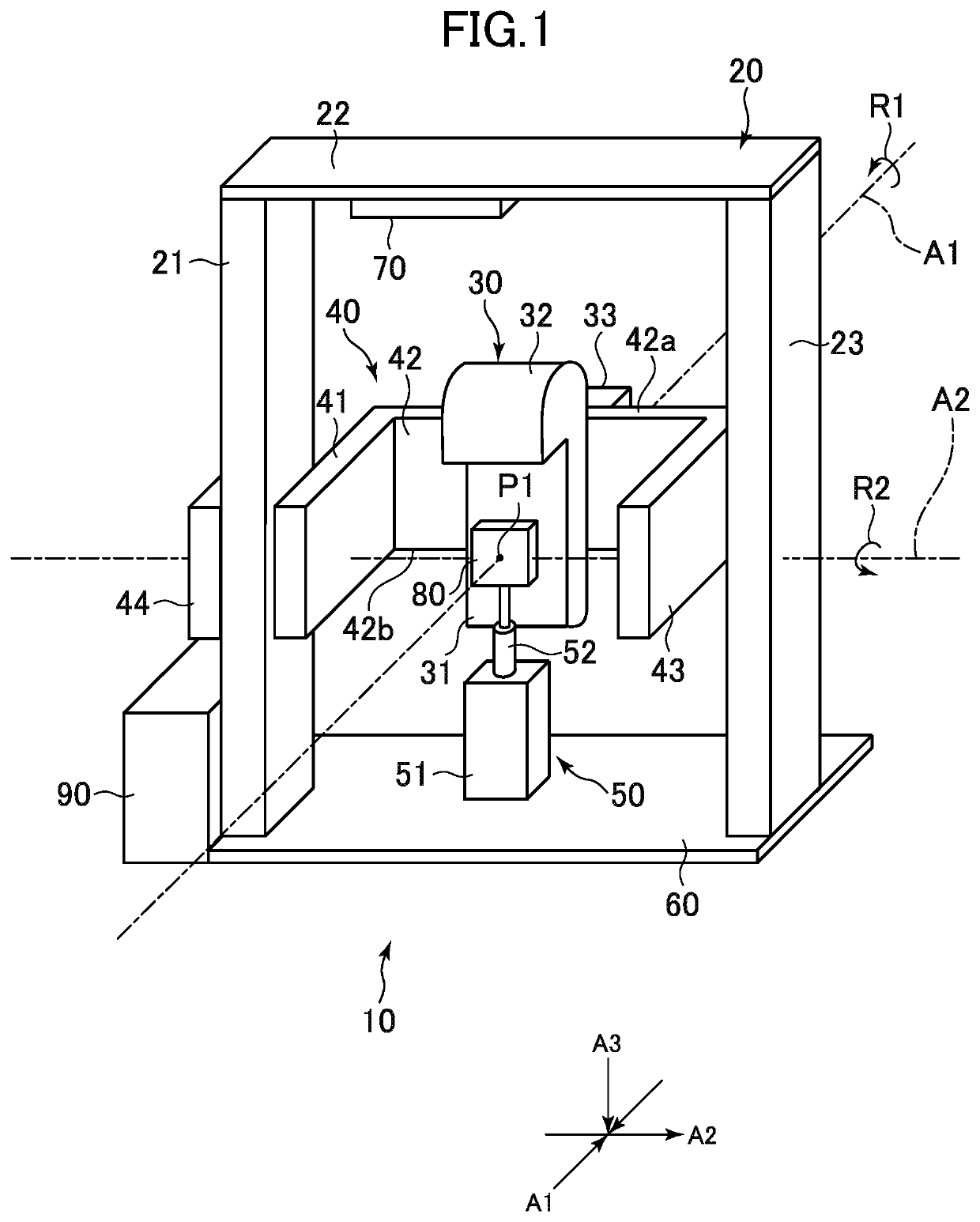
[0027]FIG. 1 is an external perspective view for illustrating a luminous body measurement apparatus according to an embodiment of the present disclosure. A luminous body measurement apparatus 10 of FIG. 1 is configured to perform near-field distribution measurement. In the luminous body measurement apparatus 10, a holding portion 50 is provided at the center of a planar stage 60 placed at a bottom portion of the luminous body measurement apparatus 10. The holding portion 50 is configured to hold a sample 80 as a luminous body such as an LED in a reference position P1. The sample 80 is connected to power supply wiring (not shown) and is allowed to emit light at any timing. The holding portion 50 includes an adjustment mechanism 51 placed at the center of the stage 60, and a holding bar 52 is mounted to the adjustment mechanism 51 so as to extend upward. The sample 80 is fixed to a...


PUM


Abstract

To provide a luminous body measurement apparatus capable of being easily downsized, with which luminance of a luminous body can be measured in a wide range on a measurement sphere. The luminous body measurement apparatus is configured to pivot a first arm and a second arm in a non-inverted posture to obtain luminance data of a sample at a plurality of image pickup positions in a first region of the measurement sphere, and is configured to pivot the first arm and the second arm in an inverted posture to obtain luminance data of the sample at a plurality of image pickup positions in a second region adjacent to the first region, the non-inverted posture being a posture under which a supporting portion is located on one side of an axis as viewed from a holding portion, the inverted posture being a posture under which the supporting portion is located on another side of the axis as viewed from the holding portion.

Description

CROSS-REFERENCE TO RELATED APPLICATION[0001]The present application claims priority from Japanese application JP2019-050291 filed on Mar. 18, 2019, the content of which is hereby incorporated by reference into this application.BACKGROUND OF THE INVENTION1. Field of the Invention[0002]The present invention relates to a luminous body measurement apparatus and a luminous body measurement method, and more particularly, to a luminous body measurement apparatus and a luminous body measurement method, with which luminance data of a luminous body is obtained at a plurality of image pickup positions on a measurement sphere, and light distribution characteristic of the luminous body is calculated based on the luminance data obtained at the plurality of image pickup positions.2. Description of the Related Art[0003]The light distribution characteristic indicating the direction and intensity of light to be emitted from the luminous body is important information for designing lighting. For exampl...

Claims


Application Information

Patent Timeline
IPC IPC(8): G01J1/42G01J1/04
CPCG01J2001/4252G01J1/0403G01J1/42G01J1/00G01J1/0411G01J1/0266G01J1/0414G01J1/44
Inventor NISHIDA, YOSHIHIKOSANO, HIROYUKI
Owner OTSUKA DENSHI CO LTD
Learn More