Heterogeneous integrated high voltage DC/AC light emitter

a light emitter and high voltage technology, applied in the field of light emitting devices, can solve the problems of low product yield and reliability, inefficient light extraction, thermal dissipation, etc., and achieve the effect of enhancing thermal dissipation and light extraction

Active Publication Date: 2006-07-27
LED LIGHTING
View PDF5 Cites 275 Cited by
  • Summary
  • Abstract
  • Description
  • Claims
  • Application Information

AI Technical Summary

Benefits of technology

[0008] The present invention provides an improved III-nitride semiconductor based high voltage DC / AC light emitting device by heterogeneously integrating an array of LEDs with a passive / active submount through flip-chip bonding or other mounting method. The submount may be aluminum nitride, boron nitride, or other appropriate materials with both insulating and thermal conductivity properties. The submount may include flip-chip bumps for bonding the LED array and enhancing the thermal dissipation and light extraction. The submount may also include passive circuits to serially interconnect the discrete LED array and provide current limiting protection. Furthermore, the submount may also be silicon with an active control circuit on one side and insulating and metal layers to connect the LED array on the other side. The final device has two or more outlet connections for the supplied power (and control signals). The supplied power may be 12V, 24V or other DC voltages, or it may be an AC voltage such as 110 / 120V or 220 / 240V. The light emission may be white light, a single color, multiple colors or time-varying color.

Problems solved by technology

Several problems with prior art integrated LEDs include inefficient light extraction, thermal dissipation, and low product yield and reliability.
An inconsistent or thin metal layer 28 may cause leakage or disconnection at the trench side walls 38, which may result in product performance, yield and reliability degradation.
Unfortunately, sapphire has a very low thermal conductivity and the limited thermal dissipation degrade the high voltage (and high power) LED device performance and lifetime.
Another drawback for the prior art is that the light is extracted from the epilayer device side and a significant portion of the light is blocked and absorbed by the metal layers, including the p-contact 20, n-contact 22, metal layer 28 and the current spreading layer 24 limiting the light emitting efficiency.

Method used


Image

  • Heterogeneous integrated high voltage DC/AC light emitter
  • Heterogeneous integrated high voltage DC/AC light emitter
  • Heterogeneous integrated high voltage DC/AC light emitter

Examples


Embodiment Construction

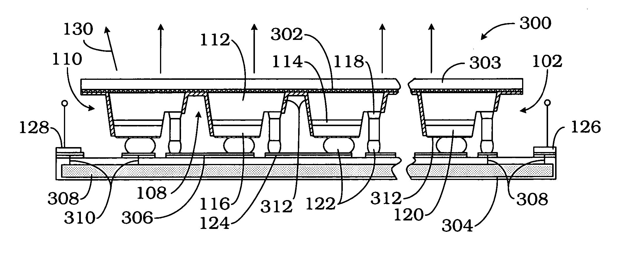
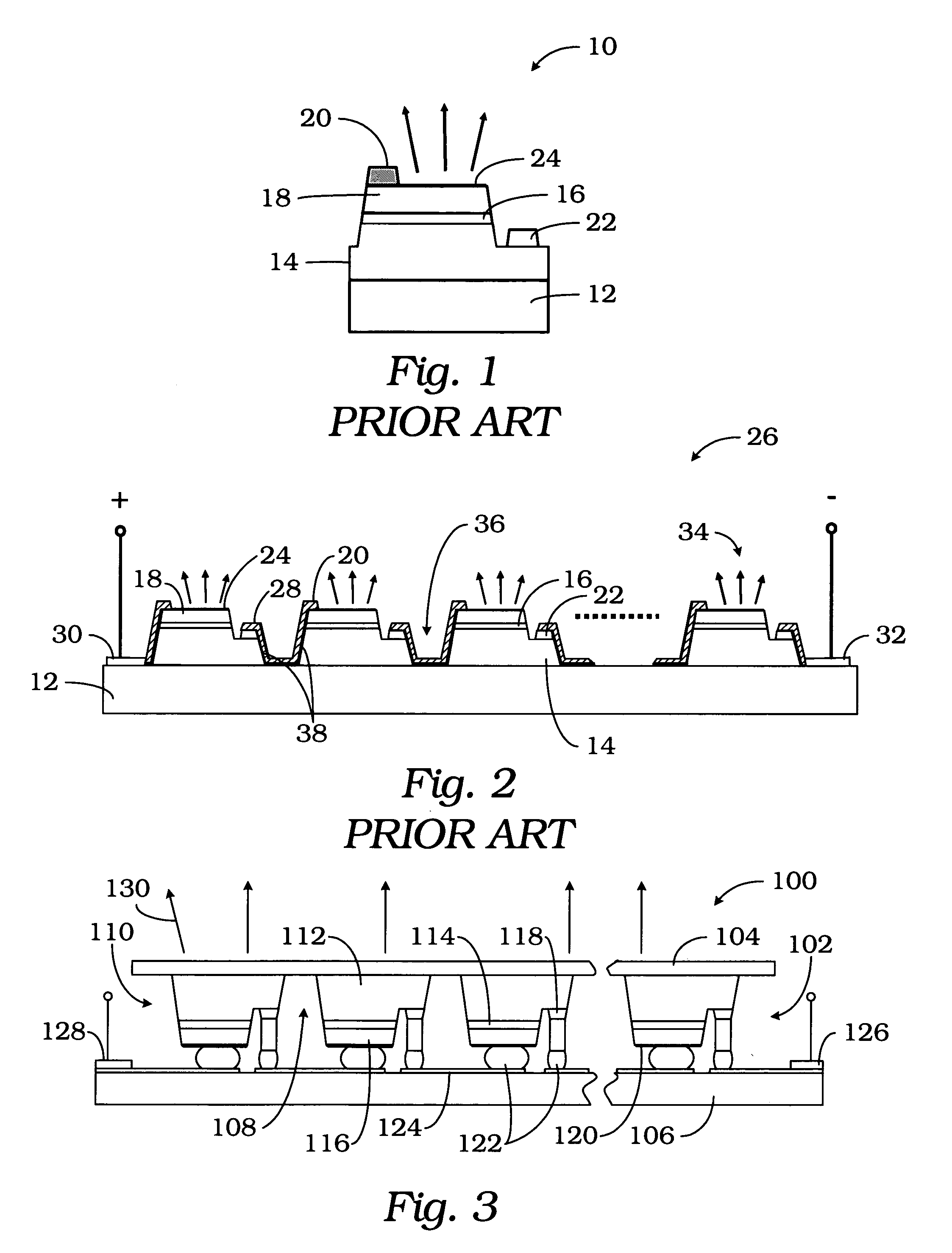
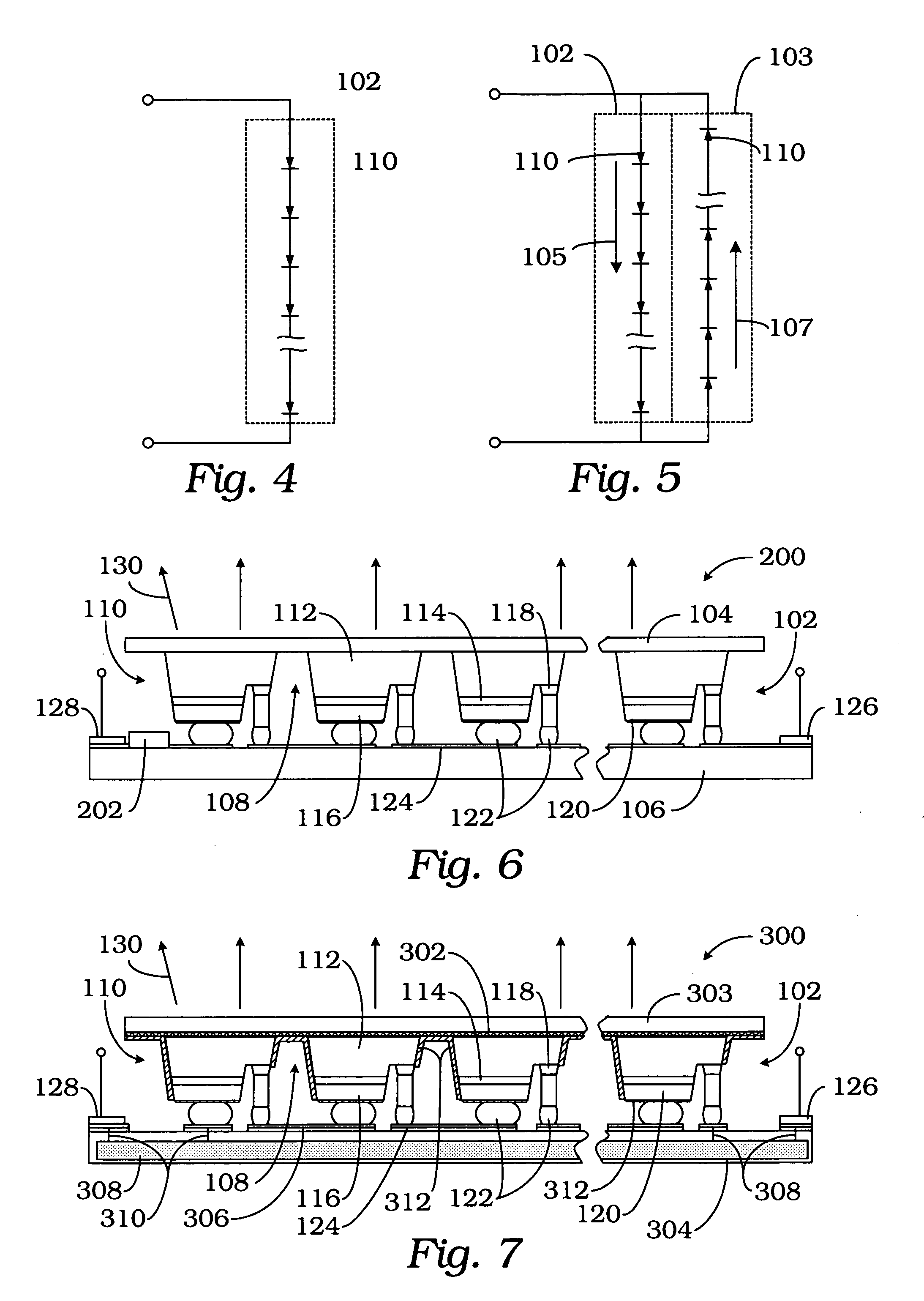
[0018] Referring to FIG. 3, a chip-scale high voltage DC / AC light emitting device is generally indicated by reference numeral 100. The high voltage DC / AC light emitting device 100 is built by heterogeneously integrating a laterally conducting InGaAlN LED array 102 fabricated on a substrate 104 with a submount or mount assembly 106. The array 102 is connected to the submount assembly 106 by flip-chip bonding or other connection method. The substrate 104 may be transparent, semi-transparent, translucent or have similar properties to allow light to be extracted from the substrate. Substrate may be an insulating material such as sapphire (Al2O3), SiC, Si, GaAs, for example. By flip-chip bonding with the semiconductor epilayers facing down to the submount 106, the light will be extracted from the substrate 104 of the LED array 102. By moving more metal layers from the LED array die to the submount, this invention will also improve the light extraction efficiency. It should be understood ...


PUM


Abstract

A single-chip integrated LED particularly adapted for direct use with a high voltage DC or AC power sources comprises a plurality of electrically isolated LEDs on a generally transparent substrate and bonded to electrically conductive elements on a thermally conductive mount. A reflective coating may be applied to the area between LEDs.

Description

[0001] The U.S. Government has a paid-up license in this invention and the right in limited circumstances to require the patent owner to license others on reasonable terms as provided for by the terms of Contract No. N00014-02-C-0214 awarded by the Office of Naval Research.BACKGROUND OF THE INVENTION [0002] The present invention relates to a light emitting device, and more particularly, to a heterogeneously integrated light emitting device which may be directly powered by a high DC voltage or by an AC voltage for general lighting, indication or display purposes. [0003] The advances in III-Nitride semiconductors (including GaN, InN, AlN and their alloys) based light emitting diodes (“LEDs”) is dramatically changing the lighting technology with a new lighting paradigm. LEDs, which have been until recently mainly used as simple indicator lamps in electronics and toys, now have the great potential to replace incandescent light bulbs in many applications, particularly those requiring dur...

Claims


Application Information

Patent Timeline
Patent Type & Authority Applications(United States)
IPC IPC(8): H01L33/00F21K99/00
CPCF21K9/00H01L27/156H01L2224/11H01L27/153H01L2224/05573H01L2224/05568H01L2924/00014H01L2224/0554H01L2224/05599H01L2224/0555H01L2224/0556
Inventor FAN, ZHAOYANGJIANG, HONGXINGLIN, JINGYU
Owner LED LIGHTING
Why Eureka
Try Eureka