Unmanned aerial vehicle off-site landing system

a technology of off-site landing and unmanned aerial vehicles, which is applied in the field of aircraft, can solve the problems of low safety standards of unmanned aerial vehicles compared to manned aircraft, and still exist potential damage to people and property on the ground, so as to reduce the ability of uav, reduce collateral damage to ground elements, and effectively land

Active Publication Date: 2020-10-01
HONEYWELL INT INC
View PDF0 Cites 1 Cited by
  • Summary
  • Abstract
  • Description
  • Claims
  • Application Information

AI Technical Summary

Benefits of technology

117]Accordingly, the off-site landing system 120 of the UAV 100 is able to effectively land the UAV 100 at landing sites or even at off-site landing sites during certain failures while also generating trajectories which minimize collateral damage to ground elements when the failures of the UAV 100 reduce the ability of the UAV to perform the landing.<

Problems solved by technology

Due to the nature of the unmanned aerial vehicles, namely that there are no passengers aboard the vehicle, unmanned aerial vehicles typically have lower safety standards when compared to manned aircraft.
While lower safety standards may be acceptable for the unmanned aerial vehicles itself, the potential for damage to people and property on the ground still exists when the unmanned aerial vehicle experiences a failure.

Method used


Image

  • Unmanned aerial vehicle off-site landing system
  • Unmanned aerial vehicle off-site landing system
  • Unmanned aerial vehicle off-site landing system

Examples


Embodiment Construction

[0012]The following detailed description is merely exemplary in nature and is not intended to limit the invention or the application and uses of the invention. As used herein, the word “exemplary” means “serving as an example, instance, or illustration.” Thus, any embodiment described herein as “exemplary” is not necessarily to be construed as preferred or advantageous over other embodiments. All of the embodiments described herein are exemplary embodiments provided to enable persons skilled in the art to make or use the invention and not to limit the scope of the invention which is defined by the claims. Furthermore, there is no intention to be bound by any expressed or implied theory presented in the preceding technical field, background, brief summary, or the following detailed description.

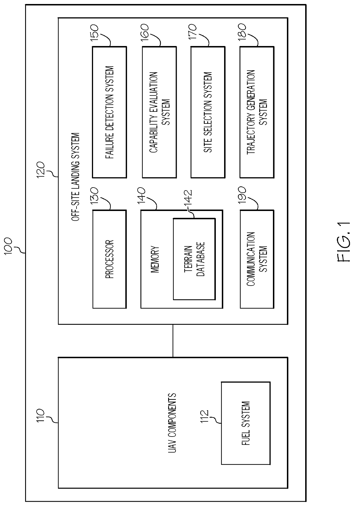
[0013]An unmanned aerial vehicle and an off-site landing system therefore is discussed herein. The off-site landing system detects faults in components of the unmanned aerial vehicle and determ...


PUM


Abstract

A fixed wing unmanned aircraft and a method for operating the same are provided. The fixed wing unmanned aircraft may include, but is not limited to, a failure detection system configured to detect faults in one or more of the plurality of components, a capability evaluation system communicatively coupled to the failure detection system, the capability evaluation system configured to determine a capability level of the fixed wing unmanned aerial vehicle based upon the faults in the one or more of the plurality of components, and a trajectory generation system communicatively coupled to the failure detection system and the capability evaluation system, the trajectory generation system configured to generate a touch down trajectory for the fixed wing unmanned aerial vehicle based upon the determined capability level of the fixed wing unmanned aerial vehicle, wherein when the determined capability level is below a predetermined threshold, the touch down trajectory comprising a stall maneuver configured to minimize a lateral energy of the fixed wing unmanned aerial vehicle.

Description

TECHNICAL FIELD[0001]The present disclosure generally relates to an aircraft, and more particularly relates to unmanned aerial vehicles and the landing thereof.BACKGROUND[0002]Unmanned aerial vehicles have an expanding role in the transportation of cargo, surveillance and a variety of other uses. Due to the nature of the unmanned aerial vehicles, namely that there are no passengers aboard the vehicle, unmanned aerial vehicles typically have lower safety standards when compared to manned aircraft. While lower safety standards may be acceptable for the unmanned aerial vehicles itself, the potential for damage to people and property on the ground still exists when the unmanned aerial vehicle experiences a failure.BRIEF SUMMARY[0003]In one embodiment, for example, a fixed wing unmanned aerial vehicle is provided. The fixed wing unmanned aerial vehicle may include, but is not limited to, a failure detection system configured to detect faults in one or more of the plurality of components,...

Claims


Application Information

Patent Timeline
Patent Type & Authority Applications(United States)
IPC IPC(8): G08G5/02G08G5/00G05B23/02B64D37/26B64C39/02
CPCG08G5/025G08G5/0056G05B23/0218B64C2201/12B64C39/024B64C2201/104B64D37/26B64C39/00G05D1/0676G05D1/101G08G5/0021G08G5/0069G08G5/0039B64D2045/0085B64U10/25B64U2201/10B64U70/00B64U30/10B64U2101/00
Inventor LIU, YANGHICKMAN, ALAN BRUCECHEN, XIAODONGCHEN, SHUAIFENG, WENWANZHANG, LEIZOU, YUNFEI
Owner HONEYWELL INT INC
Why Eureka
Try Eureka