Internal reinforcement and confinement structure for warheads

a technology of confinement structure and warhead, which is applied in the direction of projectiles, weapons, ammunition projectiles, etc., can solve the problems of significant design, performance and safety problems, additional problems, and reduce the effectiveness of the warhead, so as to efficiently deliver the warhead payload to the target, maintain the integrity of the warhead, and minimize collateral damage

Inactive Publication Date: 2016-08-11
US SEC THE ARMY THE
View PDF1 Cites 0 Cited by
  • Summary
  • Abstract
  • Description
  • Claims
  • Application Information

AI Technical Summary

Benefits of technology

[0015]In operation, the structure supports the dense high explosive against deformation during launch and thus maintains the integrity of the warhead. The structure does this through a combination of load transfer between the dense high explosive and the support structure and confinement of the high explosive by the support structure. Upon detonation, the detonation wave, which travels in a direction parallel to the walls of the support structure and therefore the support structure does not disturb the detonation process in contrast to the baffle support described previously. The effective result of the support structure is that the warhead is structurally capable of surviving gun launch while also efficiently delivering the warhead payload to the target while simultaneously minimizing collateral damage.

Problems solved by technology

The use of the thin metallic or polymer composite warhead outer shell and / or dense high explosives, however, creates significant design, performance, and safety issues during gun launch.
However, simply increasing the strength of the warhead outer shell alone creates additional problems.
If the burst strength of the outer shell is too large, the explosive blast at the target is largely contained within the warhead thus reducing its effectiveness.
Conversely, if the burst strength is too weak, the munition structurally fails in bore during the gun launch due to the loading created by the Poisson effect and a serious safety hazard results.
Consequently, the goal is to design the outer shell strength of the warhead such that the warhead maintains its structural integrity during launch, but fails in the vicinity of the target during the explosive blast.
As such, these baffles may disadvantageously reduce the detonation propagation from one high explosive volume to the neighboring high explosive volume across the baffle support structure.
In addition to the concern of detonation propagation, a primary disadvantage of this approach, however, is that the overall amount of explosive is reduced, thus reducing the overall effectiveness of the warhead.
Addtionally, the supporting baffle structure is likely to unintentionally add significant lethality to the low collateral warhead.

Method used


Image

  • Internal reinforcement and confinement structure for warheads
  • Internal reinforcement and confinement structure for warheads
  • Internal reinforcement and confinement structure for warheads

Examples


Embodiment Construction

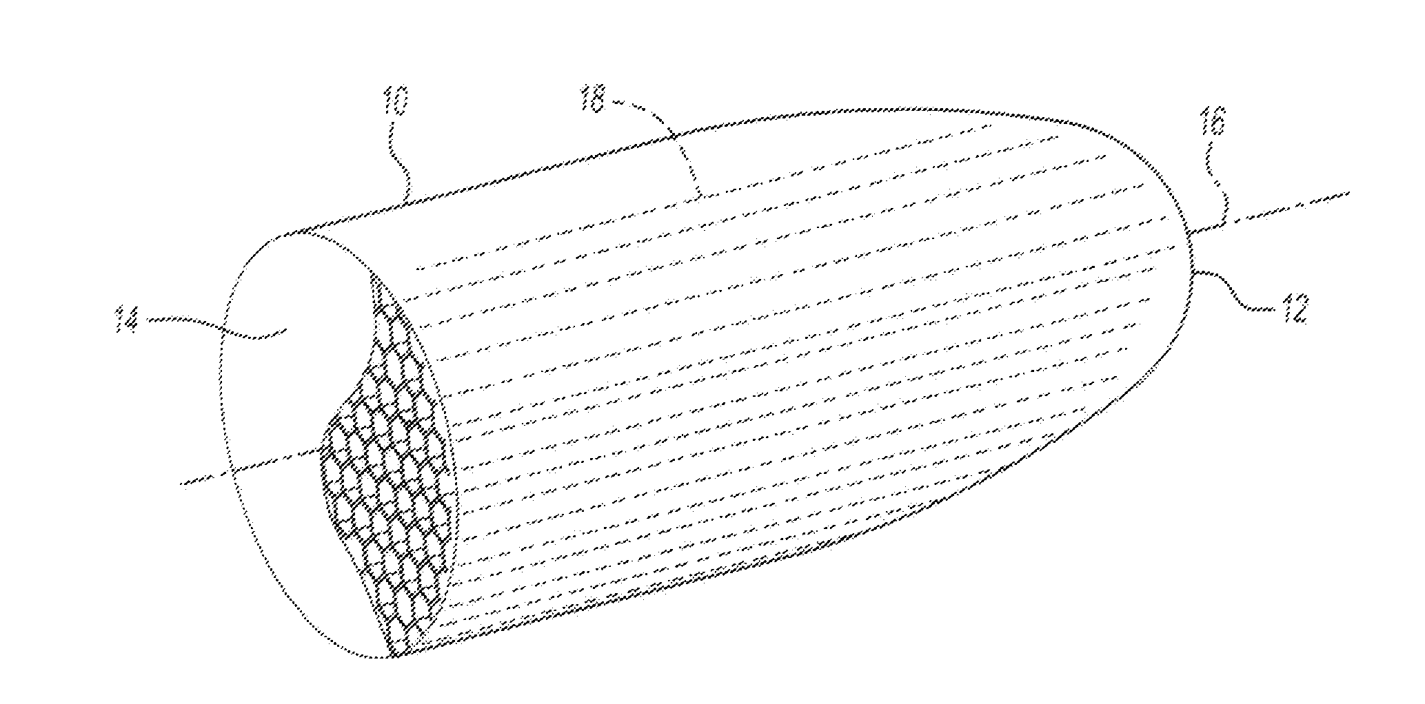
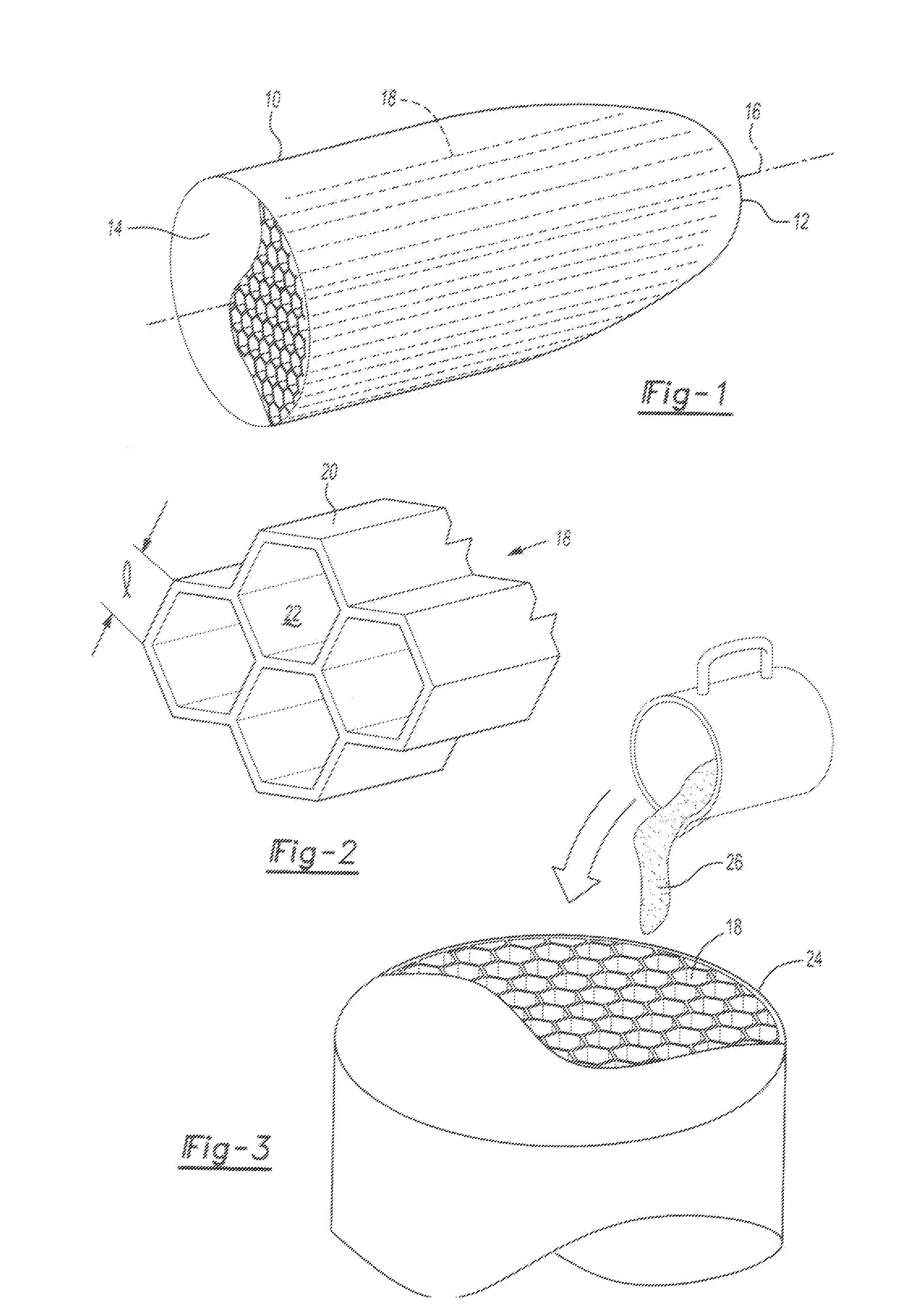
[0020]With reference first to FIG. 1, an exemplary warhead 10 is shown having both a front end 12 and a base end 14. The warhead 10 is adapted to be gun launched along a launch axis 16 from a gun toward the target.

[0021]With reference now to FIGS. 1 and 3, the warhead 10 includes a support structure 18 positioned within a tubular and cylindrical outer wall 24 of the warhead 10. The support structure includes a plurality of chamber (cell) walls 20 which, together, form a plurality of chambers 22 each of which is elongated in the direction of the launch axis 16. Each chamber 22, furthermore, is a closed chamber and thus isolated from its adjacent chambers 22 by the chamber (cell) wall 20. Preferred embodiments of the present invention do not require multipoint detonation. Thus, each chamber or at least a majority of the chambers should have a cross section greater than the critical detonation cross section area required for stable, sustainable detonation of the explosive contained wit...


PUM


Abstract

A warhead which is adapted to be launched in a predetermined axial direction includes a support structure having a plurality of walls which extend in a direction parallel to the predetermined axial direction. The support structure forms a plurality of closed chambers which are laterally spaced apart from each other and are elongated in the axial direction. A high explosive is contained within the structure cavities.

Description

CROSS-REFERENCE TO RELATED APPLICATIONS[0001]This application is a continuation-in-part of -pending U.S. patent application Ser. No. 13 / 672,762 filed on Nov. 9, 2012 by inventor Michael A. Minnicino II titled “Warhead” which is related to and claims priority from co-pending U.S. Provisional Patent Application No. 61 / 562,732 filed on Nov. 22, 2011 by inventor Michael A. Minnicino II titled “Reinforcement of Dense High-Explosives for Gun-Launch Applications” which are all hereby incorporated herein by reference in their entirety including all attachments, appendices and figures filed with U.S. Provisional Patent Application No. 61 / 562,732 and U.S. patent application Ser. No. 13 / 672,762.GOVERNMENT INTEREST[0002]The invention described herein may be manufactured, used, and licensed by or for the United States Government.BACKGROUND OF THE INVENTION[0003]I. Field of the Invention[0004]The present invention relates generally to items requiring structural support and geometric alignment whe...

Claims


Application Information

Patent Timeline
Patent Type & Authority Applications(United States)
IPC IPC(8): F42B12/20
CPCF42B33/0214F42B12/207
Inventor MINNICINO, II, MICHAEL A.
Owner US SEC THE ARMY THE
Why Eureka
Try Eureka