Knotless suture lock and bone anchor implant method

a technology of bone anchor and lock, which is applied in the field of knotless suture lock and bone anchor, can solve the problems of arduous and technically demanding endoscopic knot tie-in, and achieve the effect of maintaining the integrity of the loop and increasing the frictional force on the sutur

Inactive Publication Date: 2010-03-23
ARTHROCARE
View PDF338 Cites 176 Cited by
  • Summary
  • Abstract
  • Description
  • Claims
  • Application Information

AI Technical Summary

Benefits of technology

[0021]In yet another aspect of the invention, there is provided a bone anchor device for attaching connective tissue to bone, which comprises an anchor body having a distal end and a proximal end. A stem extends proximally from the proximal end of the anchor body. A deployable flap is disposed on the proximal end of the anchor body, and a notch on the anchor body is disposed at a location joining the anchor body and the deployable flap. The notch is adapted to cause the deployable flap to deploy outwardly when force is applied to a proximal end of the deployable flap by an actuator which moves distally relative to the deployable flap.
[0026]In a further aspect, the present suture lock and bone anchor combination is an embeddable bone anchor adapted to attach tissue to bone without a suture knot on the tissue by suturing the tissue without tying a suture knot on the tissue, and cinching the suture onto the anchor such that the anchor can be embedded into the bone to reattach the tissue to the bone. The loop is formed on the anchor by fixing the standing leg portion of the suture distally in the anchor and threading the working leg portion of the loop through holes in the anchor. On pulling on the working leg portion, the suture tightens on the anchor to cinch the loop and tissue to the anchor, without forming a knot on the tissue. The anchor is adapted such that, on embedding the anchor in the bone, the standing leg portion of the suture is located distally in the bone, and the working leg portion projects out of the bone. Barbs on the anchor resist pullout of the anchor from the bone; the barbs also increase the frictional force on the suture in the bone to maintain the integrity of the loop.

Problems solved by technology

Endoscopic knot tying is an arduous and technically demanding task.

Method used


Image

  • Knotless suture lock and bone anchor implant method
  • Knotless suture lock and bone anchor implant method
  • Knotless suture lock and bone anchor implant method

Examples


Embodiment Construction

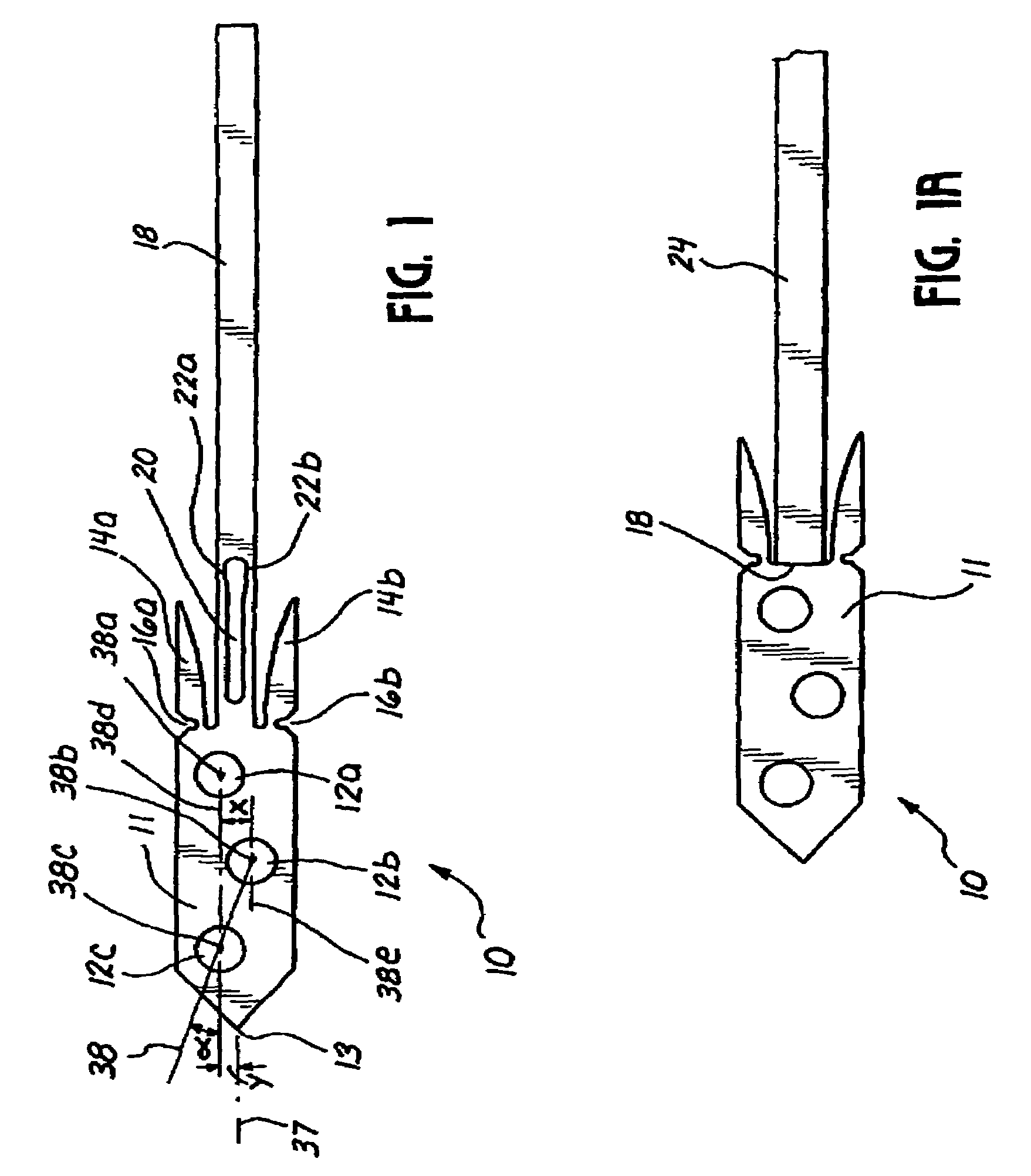
[0047]Referring now more particularly to the drawings, there is shown in FIG. 1 a bone anchor 10 in its undeployed state. The distal end of the bone anchor 10 is comprised of a substantially flat body 11 which preferably has three eyelet holes or suture retaining apertures 12a, 12b, and 12c, and which comes to a point 13 at a distal end where it is to be inserted into the bone. Two deployable flaps 14a, 14b are defined by two notches 16a,b which allow for deployment of the flaps, and are disposed at a point where the flaps 14a, 14b are attached to the flat body 11. To a proximal end of the bone anchor is joined a relatively narrow stem 18. A slit 20 is disposed at least partially on the stem 18 and partially on the flat body 11, although in presently preferred embodiments, the slit 20 is disposed entirely on the stem 18, as shown in FIG. 1. Weak links 22a, 22b are formed on either side of the slit 2.

[0048]As shown in FIG. 1a, the proximal end of the stem 18 of the bone anchor 10 is ...


PUM


Abstract

A knotless suture lock and bone anchor wherein a suture, looped through a tissue, is threaded through a plurality of body holes in the anchor to cinch the suture and tissue to the anchor without tying a suture knot on the tissue, and wherein the anchor is adapted for embedding in a bone. The tissue is secured to the anchor by suturing the tissue without a suture knot, fastening the standing leg portion of the suture on a suture leg-anchoring structure, and threading the working leg portion of the suture through the body holes. Pulling on the working leg portion of the suture tightens the suture on the body structure and cinches the loop without a suture knot on the tissue. The bone-embedding structure comprises a plurality of barbs adapted to resist pullout of the anchor from the bone.

Description

CROSS-REFENCE TO RELATED APPLICATIONS[0001]This Application is a Continuation-in-part of commonly assigned U.S. patent application Ser. No. 10 / 690,438 filed on Oct. 21, 2003, now abandoned, herein incorporated by reference in its entirety for all purposes.FIELD OF INVENTION[0002]This invention in one aspect pertains to a knotless suture lock and bone anchor, in particular a knotless suture lock and bone anchor combination wherein a suture, looped through a tissue, is threaded through a plurality of body holes in the anchor to cinch the suture and tissue to the anchor without tying a suture knot on the tissue, and wherein the anchor is adapted for embedding in a bone.BACKGROUND[0003]This invention relates generally to methods and apparatus for attaching soft tissue to bone, and more particularly to anchors and methods for securing connective tissue, such as ligaments or tendons, to bone. In one aspect the invention has particular application to arthroscopic surgical techniques for re...

Claims


Application Information

Patent Timeline
Patent Type & Authority Patents(United States)
IPC IPC(8): A61B17/04
CPCA61B17/0401A61B17/0487A61B2017/0409A61B2017/0412A61B2017/0414A61B2017/0417A61B2017/042A61B2017/0422A61B2017/0427A61B2017/0458A61B2017/0496
Inventor FOERSTER, SETHGORDON, NORMANVIJAY, FRANCISTRAN, MINH
Owner ARTHROCARE
Why Eureka
Try Eureka