Method and apparatus for downhole signal communication and measurement through a metal tubular

a technology of metal tubing and signal communication, which is applied in the field of subsurface earth formation investigation, systems and methods for transmitting and/or receiving a signal through a metallic tubular, can solve the problems of not being logged, increasing the cost and difficulty of wireline tool use, and the cost of wireline logging is too high, so as to achieve the effect of sealing the opening

Inactive Publication Date: 2003-06-10
SCHLUMBERGER TECH CORP
View PDF24 Cites 186 Cited by
  • Summary
  • Abstract
  • Description
  • Claims
  • Application Information

AI Technical Summary

Benefits of technology

Systems and methods are provided utilizing an improved downhole tubular having an elongated body with tubular walls and a central bore adapted to receive a run-in tool. The tubular has at least one slot formed in its wall to provide for continuous passage of a signal (e.g., electromagnetic energy) that is generated or received respectively by a source or sensor mounted on the run-in tool. The tubular also includes a pressure barrier within the central bore to maintain hydraulic integrity between the interior and exterior of the tubular at the slotted station. The tubular and run-in tool combinations provide systems and methods for downhole signal communication and formation measurement through a metallic tubular. A technique for measuring a formation characteristic utilizing a run-in tool adapted with a multi-mode end segment is provided. Techniques are also provided for effectively sealing openings on the surface of tubular members.

Problems solved by technology

Some wells may not be logged because wireline logging is too expensive, when rig time is included in the total cost.
Horizontal or deviated wells also present increased cost and difficulty for the use of wireline tools.
As with wireline logging, the use of LWD and MWD tools may not be justified due to the cost of the equipment and the associated service since the tools are in the hole for the entire time it takes to drill the section.
A disadvantage of the proposed apparatus is that the open-window mechanism directly exposes the logging tool to the rugose and abrasive borehole environment, where formation cuttings are likely to damage the logging tool and jam the window mechanism.
Downhole conditions progressively become more hostile at greater depths.
This exacerbates degradation of external or exposed logging tool components.
Thus, an open-window structure is impractical for use in a downhole environment.
A disadvantage of the apparatus proposed by the '546 application is the use of composite materials as an integral part of the drill collar.
Fatigue loading (i.e., the bending and rotating of the drill pipe) becomes an issue in drilling operations.
When the drill pipe is subjected to bending or torsion, the shapes of the voids or recesses change, resulting in stress failure and poor sealing.
The differences in material properties between the metal and composite covers are difficult to manage properly where the composite and metal are required to act mechanically as one piece, such as described in the '546 application.
Thus, the increased propensity for failure under the extreme stresses and loading encountered during drilling operations makes implementation of the described structure impractical.
In addition to high manufacturing costs, another disadvantage of this structure is that the multi-part assembly is more prone to failure under the extreme stresses encountered during drilling operations.
However, the apparatus is not designed for LWT operations.
Thus, implementation of the described system is impractical and not cost effective for many operations.
A disadvantage of the apparatus proposed by the '437 patent is the sensor's direct exposure to the damaging conditions encountered downhole.
The use of a small probe protruding through a small aperture is also impractical for resistivity logging.
However, none of these proposed systems relate to through-tubing measurement or signal transfer.

Method used


Image

  • Method and apparatus for downhole signal communication and measurement through a metal tubular
  • Method and apparatus for downhole signal communication and measurement through a metal tubular
  • Method and apparatus for downhole signal communication and measurement through a metal tubular

Examples


Embodiment Construction

In the interest of clarity, not all features of actual implementation are described in this specification. It will be appreciated that although the development of any such actual implementation might be complex and time-consuming, it would nevertheless be a routine undertaking for those of ordinary skill in the art having the benefit of this disclosure.

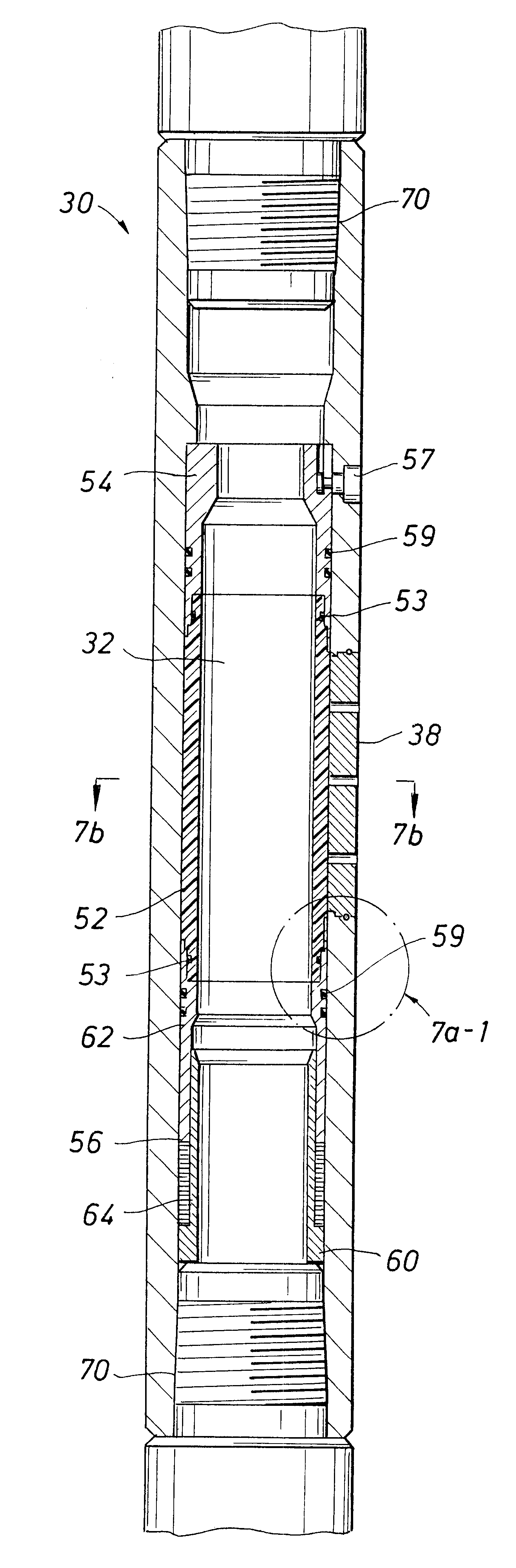
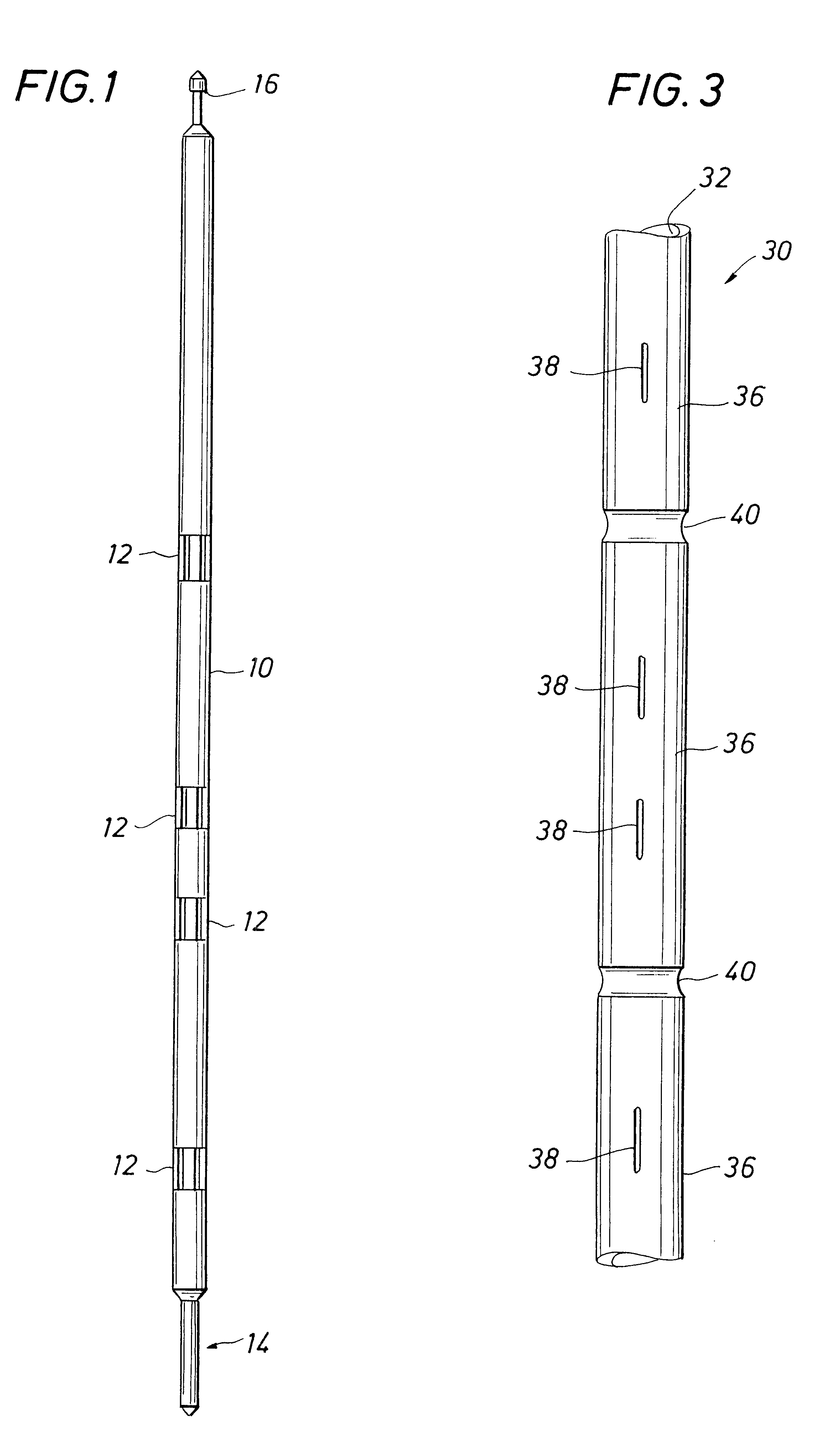
The apparatus of the invention consists of two main assets, a run-in tool (RIT) and a drill collar. Henceforth, the drill collar will be referred to as the sub.

4.1 RIT

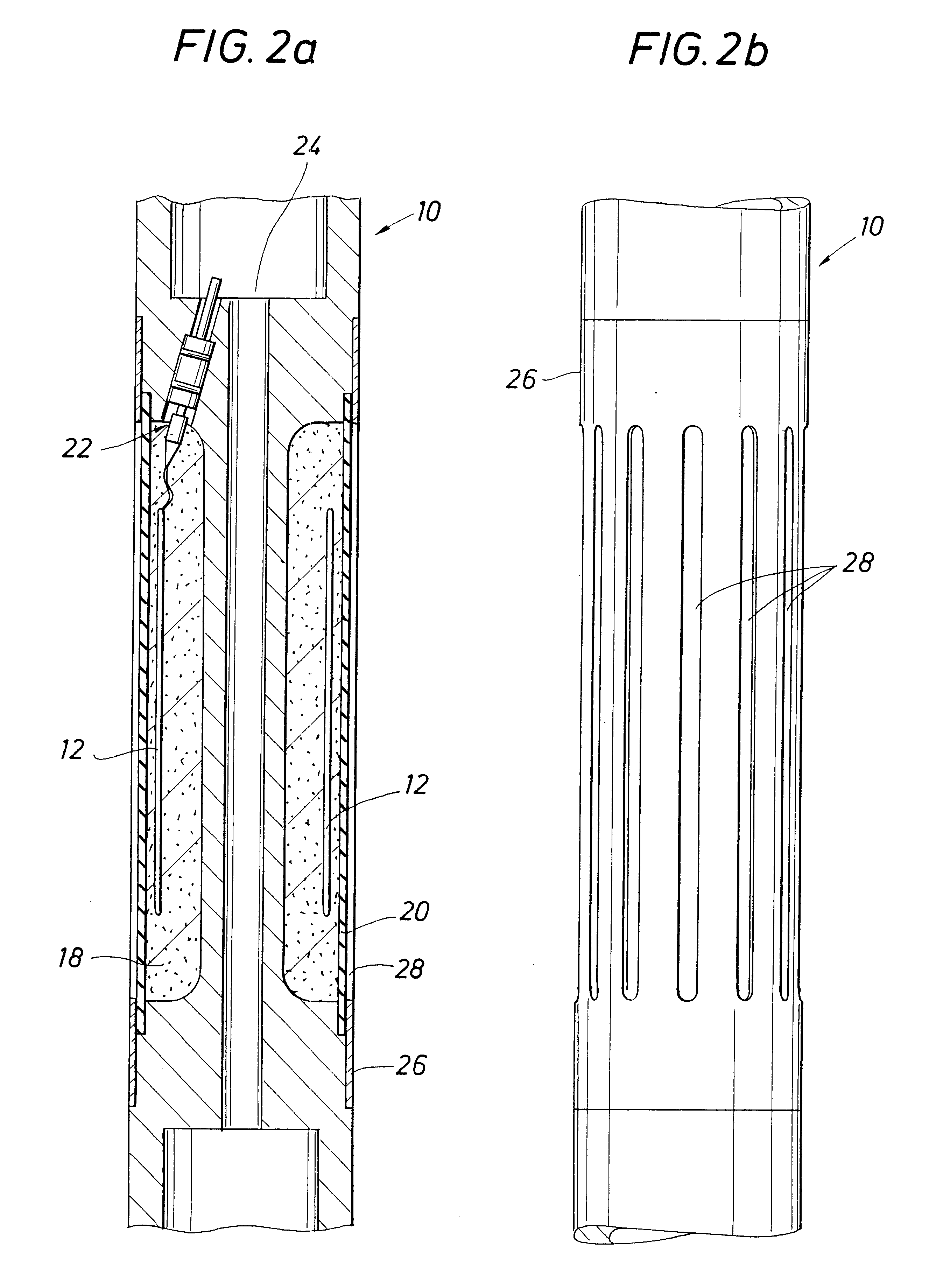
FIG. 1 shows an embodiment of the RIT 10 of the invention. The RIT 10 is an elongated, small-diameter, metal mandrel that may contain one or more antennas 12, sources, sensors [sensor / detector are interchangeable terms as used herein], magnets, a gamma-ray detector / generator assembly, neutron-generating / detecting assembly, various electronics, batteries, a downhole processor, a clock, a read-out port, and recording memory (not shown).

The RIT 10 does not have the mechanic...


PUM


Abstract

Systems and methods for downhole communication and measurement utilizing an improved metallic tubular having an elongated body with tubular walls and a central bore adapted to receive a run-in tool. The tubular including slotted stations to provide through-tubular signal transmission and / or reception. Hydraulic isolation between the interior and exterior of the tubular is provided by pressure barrier means at the slotted stations. Sensors and / or sources are mounted on the run-in tool, which is adapted for transmission through a drill string to engage within the tubular in alignment with the slotted stations. A run-in tool configuration includes a modulator for real-time wireless communication with the surface and / or remote downhole tools. A tubular and run-in tool configuration also includes inductive couplers for wireless signal data transfer. A method for measuring a formation characteristic utilizing a run-in tool adapted with an interchangeable end segment for multi-mode downhole transport. Methods for sealing an opening on the surface of a tubular having an elongated body with tubular walls and a central bore.

Description

1. BACKGROUND OF THE INVENTION1.1 Field of the InventionThis invention relates generally to investigation of subsurface earth formations, systems and methods for transmitting and / or receiving a signal through a metallic tubular, and, more particularly, to a device for receiving a run-in tool.1.2 Description of Related ArtResistivity and gamma-ray logging are the two formation evaluation measurements run most often in well logging. Such measurements are used to locate and evaluate the properties of potential hydrocarbon bearing zones in subsurface formations. In many wells, they are the only two measurements performed, particularly in low cost wells and in surface and intermediate sections of more expensive wells.These logging techniques are realized in different ways. A well tool, comprising a number of transmitting and detecting devices for measuring various parameters, can be lowered into a borehole on the end of a cable, or wireline. The cable, which is attached to some sort of m...

Claims


Application Information

Patent Timeline
Patent Type & Authority Patents(United States)
IPC IPC(8): E21B47/12E21B47/01E21B47/00G01V11/00
CPCE21B47/011G01V11/002G01V3/30E21B47/122Y10T137/0452Y10T137/0396E21B47/017E21B47/13
Inventor CLARK, BRIANHUNKA, JOHNFREY, MARK T.SMITH, DAVID L.RAMASWAMY, DHANANJAYCOLLINS, ANTHONYBONNER, STEPHEN
Owner SCHLUMBERGER TECH CORP
Why Eureka
Try Eureka