Hover-Capable Flapping-Wing Aircraft

a technology of aircraft and wings, applied in the direction of gearing, ornithopters, spars/stringers, etc., can solve the problems of reducing maneuverability and gust rejection, low reynolds number conventional rotors generally have degraded performance, and are susceptible to aerodynamic disturbances, so as to achieve greater stiffness

Active Publication Date: 2020-10-15
TEXAS A&M UNIVERSITY
View PDF0 Cites 10 Cited by
  • Summary
  • Abstract
  • Description
  • Claims
  • Application Information

AI Technical Summary

Problems solved by technology

The ability to change the direction of the lift instantaneously gives biological systems these capabilities, which rotary wing platforms are so far unable to achieve, reducing maneuverability and gust rejection.
Beyond these issues, low Reynolds number conventional rotors generally have degraded performance and can be quite susceptible to aerodynamic disturbances.

Method used


Image

  • Hover-Capable Flapping-Wing Aircraft
  • Hover-Capable Flapping-Wing Aircraft
  • Hover-Capable Flapping-Wing Aircraft

Examples


Embodiment Construction

[0037]The following discussion is directed to various exemplary embodiments. However, one skilled in the art will understand that the examples disclosed herein have broad application, and that the discussion of any embodiment is meant only to be exemplary of that embodiment, and not intended to suggest that the scope of the disclosure, including the claims, is limited to that embodiment.

[0038]Certain terms are used throughout the following description and claims to refer to particular features or components. As one skilled in the art will appreciate, different persons may refer to the same feature or component by different names. This document does not intend to distinguish between components or features that differ in name but not function. The drawing figures are not necessarily to scale. Certain features and components herein may be shown exaggerated in scale or in somewhat schematic form and some details of conventional elements may not be shown in interest of clarity and concis...


PUM


Abstract

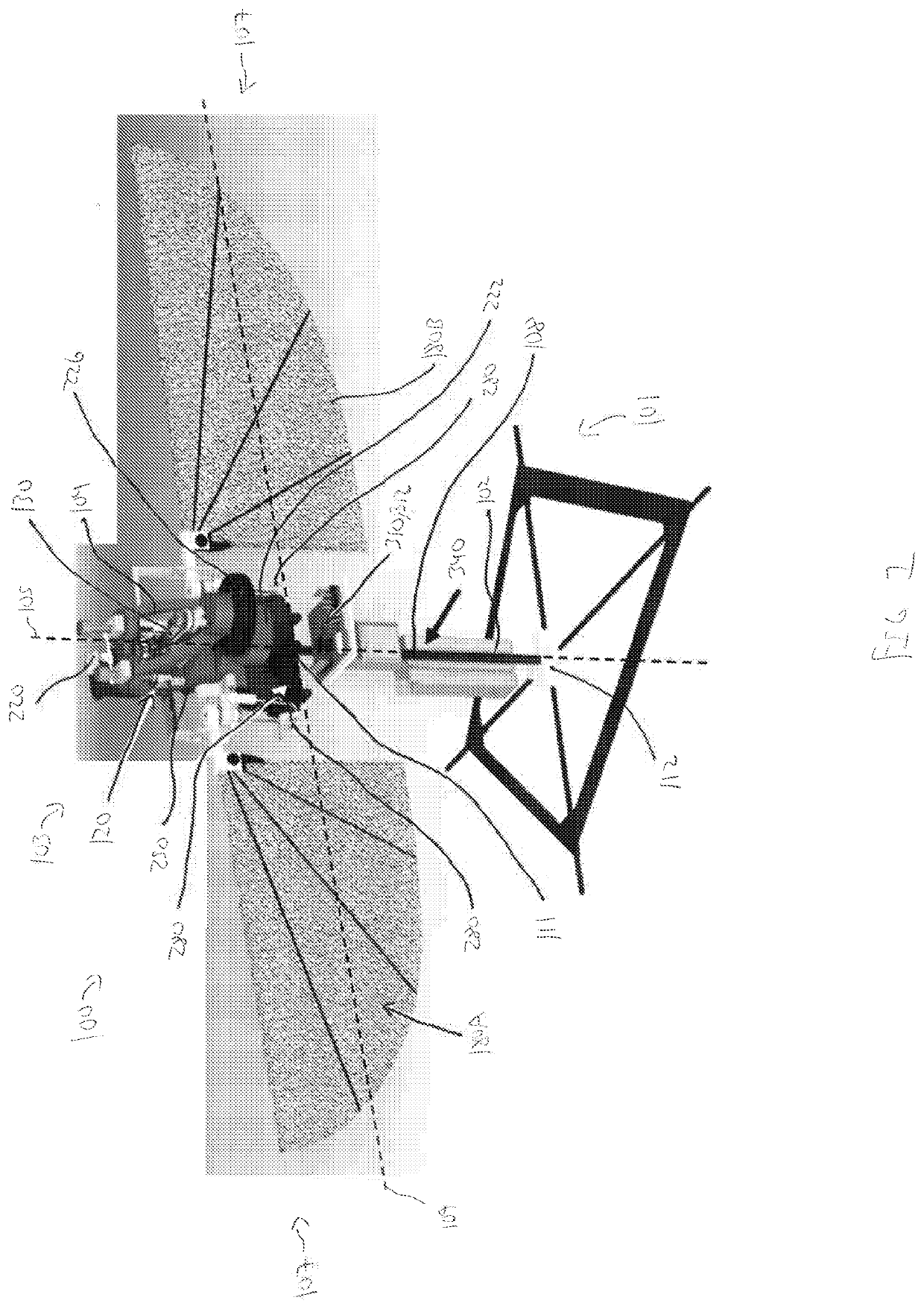
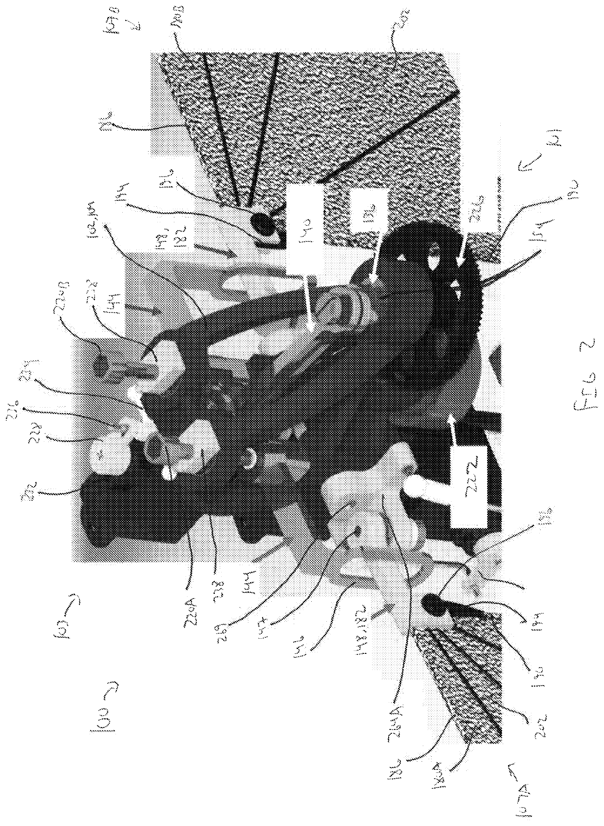
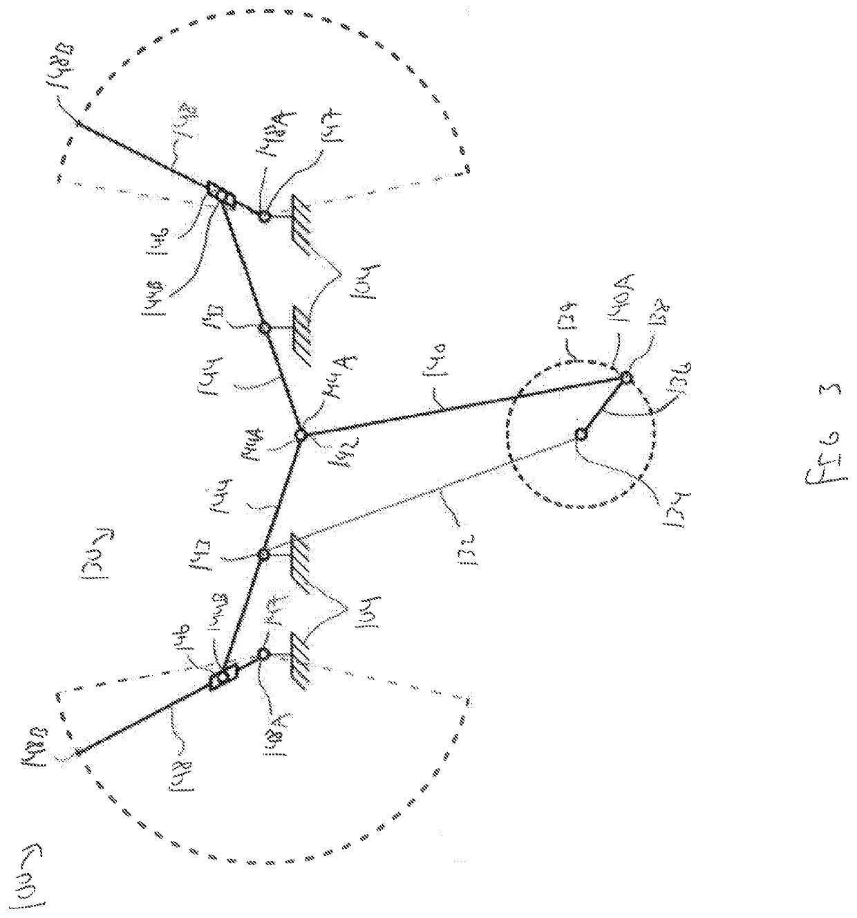
A flapping-wing aircraft includes a support frame, a motor coupled to the support frame, a pair of wings coupled to the support frame, and a linkage assembly coupled to the support frame and configured to translate an output torque of the motor into flapping motion of the wings, wherein the linkage assembly includes a first link coupled to a rotational output of the motor, a second link pivotably coupled to the first link at a first pivot joint, a third link pivotably coupled to the second link at a second pivot joint, and a fourth link pivotably coupled to the support frame and slidably coupled to the third link, and wherein the fourth link is coupled to a first wing of the pair of wings.

Description

CROSS-REFERENCE TO RELATED APPLICATIONS[0001]This application is a 35 U.S.C. § 371 national stage application of PCT / US2018 / 066809 filed Dec. 20, 2018, and entitled “Hover-Capable Flapping-Wing Aircraft,” which claims benefit of U.S. provisional patent application Serial No. 62 / 608,528 filed Dec. 20, 2017, and entitled “Hover-Capable Flapping-Wing Aircraft,” each of which is hereby incorporated herein by reference in their entirety for all purposes.STATEMENT REGARDING FEDERALLY SPONSORED RESEARCH OR DEVELOPMENT[0002]Not applicable.BACKGROUND[0003]Biomimetic, hover-capable mechanical flyers are one of the most challenging and fascinating aircraft in the development arena of new and novel micro air vehicle (MAV) platforms. While the flight line is dominated by multi-copter aircraft utilizing fixed, continuously rotating rotors, biologically-inspired two-winged, flapping-wing systems are being developed back in research hangars out of interest in the superior flight capabilities of nat...

Claims


Application Information

Patent Timeline
Patent Type & Authority Applications(United States)
IPC IPC(8): B64C33/02B64D27/24B64C19/02B64C3/18B64C3/26B64C13/18F16H21/40
CPCB64C3/26B64C33/02F16H21/40B64C13/18B64D27/24B64C19/02B64C3/185B64C39/024B64U10/40
Inventor BENEDICT, MOBLECOLEMAN, DAVID A.
Owner TEXAS A&M UNIVERSITY
Why Eureka
Try Eureka