
A vibrating screen

Active Publication Date: 2020-12-24
METSO BRASIL IND E COMML LTDA
View PDF0 Cites 2 Cited by
  • Summary
  • Abstract
  • Description
  • Claims
  • Application Information

AI Technical Summary

Benefits of technology

The present invention is a mechanical vibrator designed to provide elliptical movement to a vibrating screen. It has two shafts that rotate to create the desired movement, while a bearing case is used to transfer the motion to the screen. This design is easy to assemble and disassemble, and allows for quick maintenance or replacement. The ratio of the major and minor axes of the elliptical movement can be adjusted by adjusting the difference of eccentric mass between the two shafts. In summary, the invention provides a more efficient and effective means for creating elliptical movement for vibration screening.

Problems solved by technology

This constructive solution results in a heavy mechanical vibrator, of larger dimensions and of relatively higher cost.
Even though it presents a two-axis construction, lighter and simpler than that of three shafts, imparting to the screen deck of the vibrating screen a more efficient elliptical movement, the third known construction still presents a deficiency common to the other two previous solutions discussed above and which results from the fact that the mechanical vibrator has its bearing cases mounted through medial regions of the opposing sidewalls of the vibrating screen.
With the aforementioned constructions, the mechanical vibrator is mounted inside the structure of the vibrating screen, which makes very complex, time-consuming and costly the disassembling and assembling operations of their components for maintenance.
The maintenance operations are generally carried out, as a result of the structural incorporation of the vibrator to the vibrating screen, in highly polluted environments, making these operations even more problematic, requiring undesirable periods of operational interruption of the equipment.

Method used


Image

  • A vibrating screen
  • A vibrating screen
  • A vibrating screen

Examples


Embodiment Construction

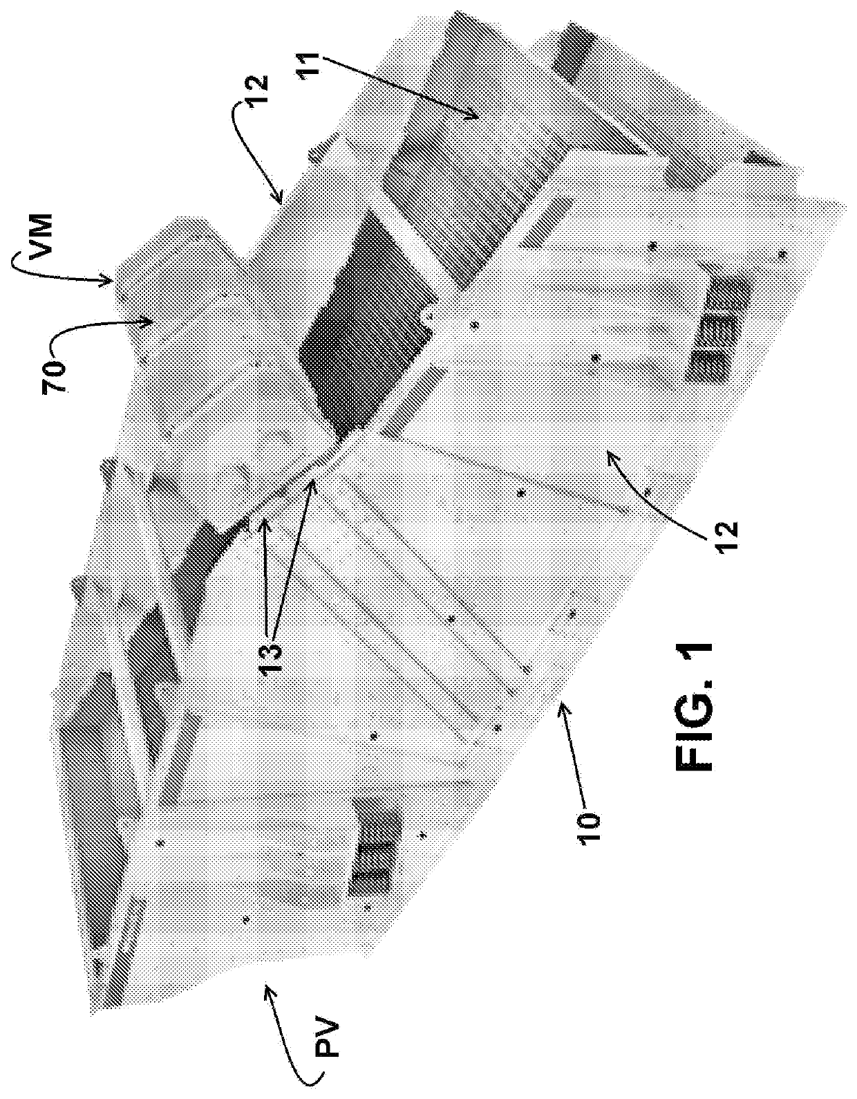
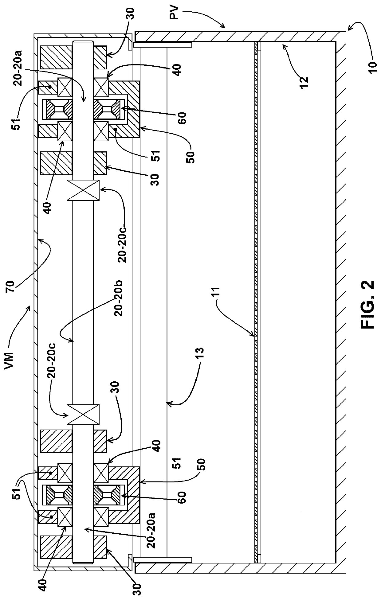
[0027]As illustrated and already mentioned above, the invention relates generally to vibrating screens PV for sorting bulk material and, more specifically, to those screens of the type comprising at least one screen element 10, generally in the form of an elongated chute and substantially U-shaped profile and having a screen deck 11 onto which is moved a continuous load of bulk material such as various ores, the screen deck 11 being defined between two sidewalls 12 of the vibrating screen PV.

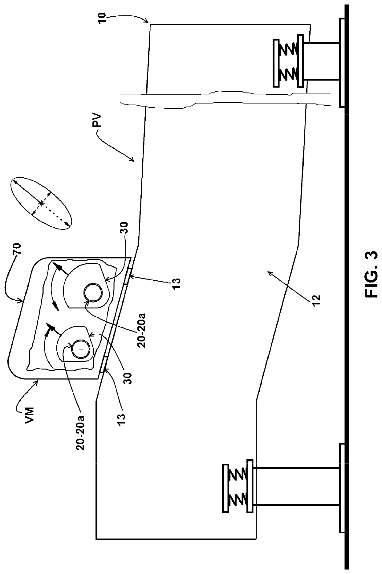
[0028]As shown, the mechanical vibrator VM comprises a pair of shafts 20 transversal to the longitudinal axis of the vibrating screen 10, each having an end portion 20a carrying at least one eccentric weight 30.

[0029]In the illustrated construction, the adjacent end portions 20a of the shafts 20 are rotatively supported on bearings 40 which are mounted in a same bearing case 50 which is removably fixed on beams 13, generally two and transversal to the longitudinal axis of the vibrating screen PV...


PUM


Abstract

The vibrating screen have a screen deck, two sidewalls and a mechanical vibrator comprising two shafts, rotating at the same rotation and in opposite directions, each one of the end portions of each shaft carrying an eccentric weight and being supported on bearings which are supported in the sidewalls of the vibrating screen. The shafts have their end portions, adjacent to each other, supported on bearings mounted to a same bearing case fixed to beams, transversal and having opposite ends fixed to the sidewalls of the vibrating screen. Each end portion of a shaft carries an eccentric weight with a total mass different from that one of the eccentric weights of the end portions of the other shaft, said shafts rotating in determined phases, defining the inclination of the major axis of an elliptical movement imparted to the screen deck.

Description

FIELD OF THE INVENTION[0001]The present invention relates to a mechanical vibrator with a bearing case mechanism to be mounted on vibrating screens for separating bulk material to vibrate a screen deck of at least one screen element, the mechanical vibrator being of the type which comprises a pair of bearing cases supported by the structural sidewalls of the vibrating screen and supporting the opposite end portions of rotating shafts which are transversal to the longitudinal axis of the vibrating screen, said end portions of the shafts carrying eccentric weights.BACKGROUND OF THE INVENTION[0002]The process of separating bulk grains or particles of different sizes in machines or vibrating screens comprises the passage of the bulk material along the screen deck of a screen element which is vibrated so that, with the displacement of the bulk material, the smaller particles pass through the holes of the screen deck, to be separately released from the larger particles being displaced ove...

Claims


Application Information

Patent Timeline
IPC IPC(8): B07B1/28B07B1/38B07B1/44
CPCB07B1/284B07B1/44B07B1/38B07B1/42B07B1/28B07B1/282
Inventor KATO, SADAOREZENDE, JR., FAUSTOOGAWA, RICARDO MAERSCHNER
Owner METSO BRASIL IND E COMML LTDA
Learn More