
Alternating current (AC)-direct current (DC) power booster and ac-DC power control module for ac and DC illuminations

a technology of ac and dc power boosters and control modules, which is applied in emergency power supply arrangements, instruments, greenhouse gas reduction, etc., can solve the problems of smps type power conversion devices, noise, surge voltage, etc., and achieves convenient installation and detachment, easy movement, and easy charging

Active Publication Date: 2015-12-03
ADC ENERGY USA INC
View PDF5 Cites 3 Cited by
  • Summary
  • Abstract
  • Description
  • Claims
  • Application Information

AI Technical Summary

Benefits of technology

The present invention is a power booster that can be easily installed and detached. It can be moved to different places to charge batteries and provide power to AC electronic appliances in case of an emergency. The power control module helps control power to improve the lifespan and reduce power consumption of AC and DC illumination instruments.

Problems solved by technology

On the other hand, AC power cannot be stored in a battery.
While the LEDs have low power consumption, they are vulnerable to an instantaneous over-voltage and over-current due to grid lines or power converting devices.
Moreover, while the SMPS type power converting devices as described above are typically used as power circuits for driving the LEDs, the SMPS type power converting devices are also vulnerable to noise and a surge voltage that may occur instantaneously and unexpectedly.
Consequently, these become the cause of defects with respect to an LED illumination load, resulting in damage to persons or assets.
Thus, regarding power supply systems that are presently used, no other benefits of using DC power are obtained other than the effect of reducing energy consumption due to the use of the LED devices having small power consumption.

Method used


Image

  • Alternating current (AC)-direct current (DC) power booster and ac-DC power control module for ac and DC illuminations
  • Alternating current (AC)-direct current (DC) power booster and ac-DC power control module for ac and DC illuminations
  • Alternating current (AC)-direct current (DC) power booster and ac-DC power control module for ac and DC illuminations

Examples


Embodiment Construction

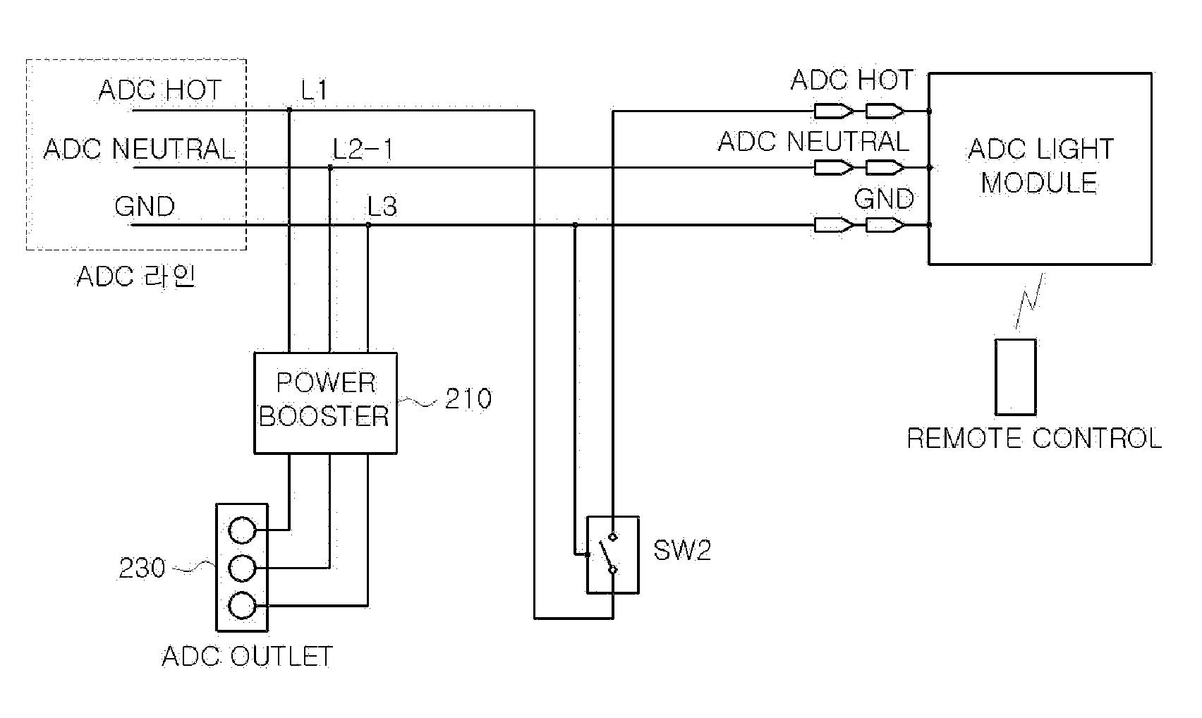
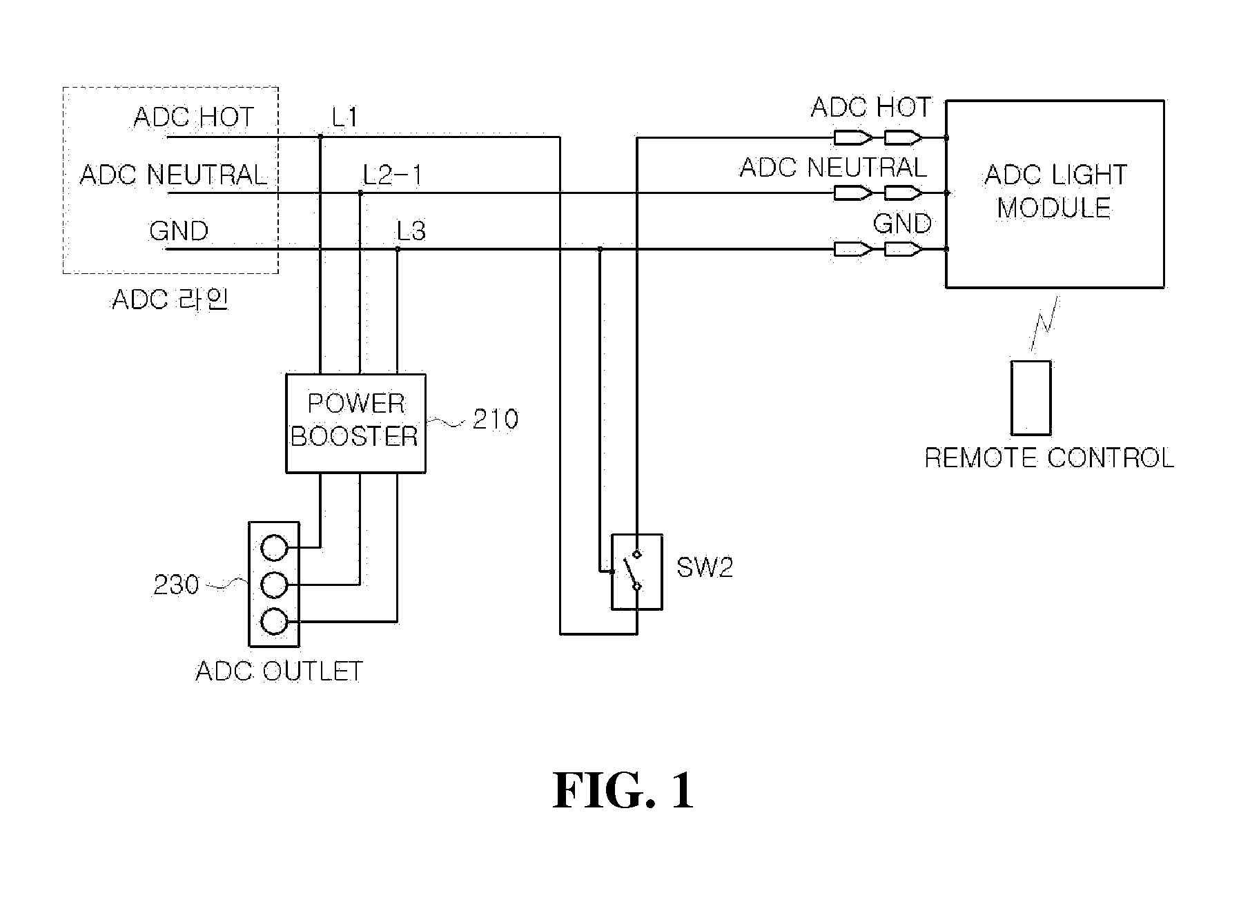
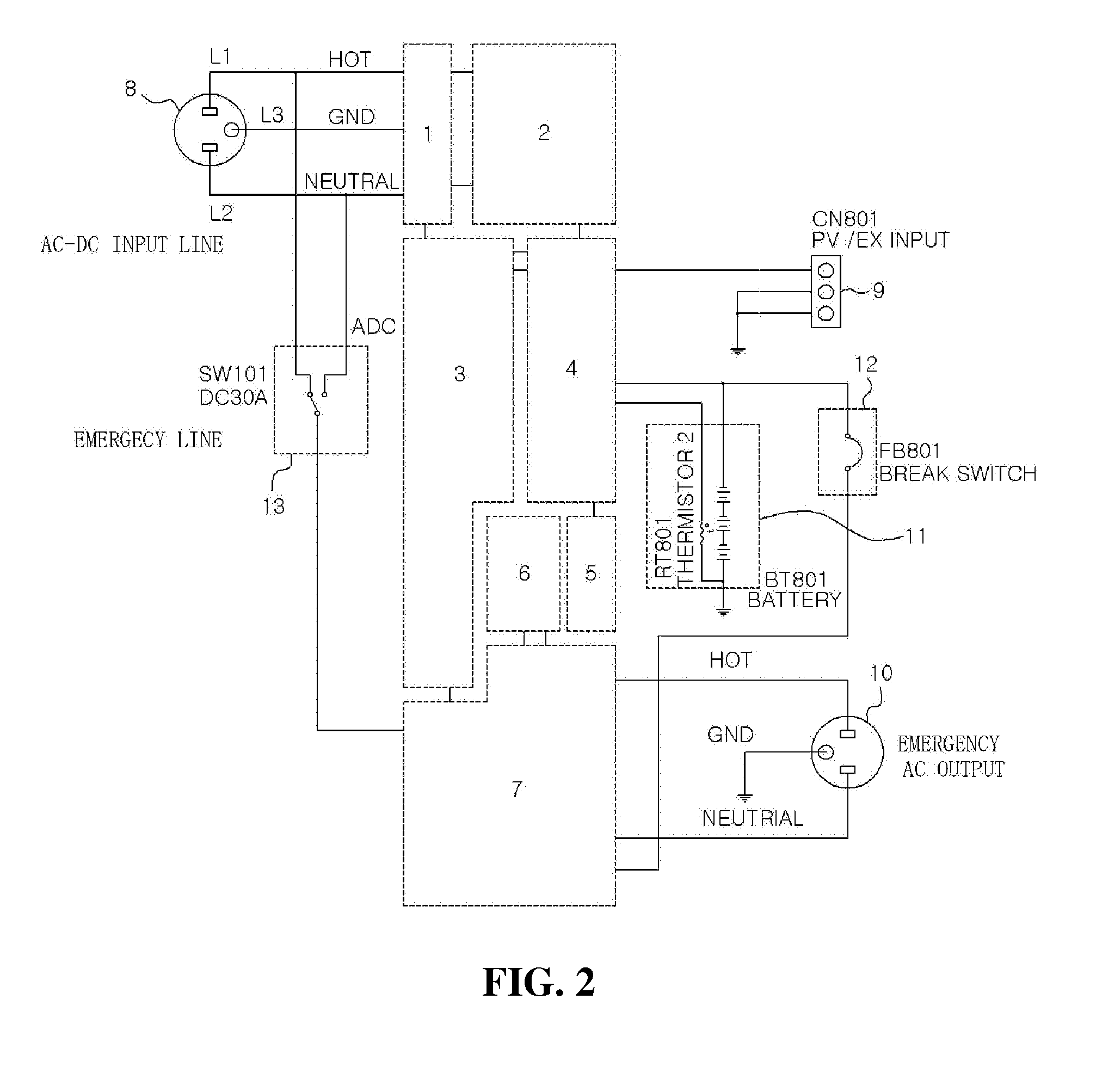
[0024]A power booster according to an embodiment of the present invention includes: an electromagnetic interference (EMI) filter circuit that is included to convert alternating current (AC) power from among applied AC power and direct current (DC) power, to DC power to be output; a power factor correction (PFC) circuit that is connected to the EMI filter circuit and stabilizes a predetermined output voltage; and a switching mode power supply (SMPS) circuit that is connected to the PFC circuit and applies the DC power of the PFC circuit to a drain of the SMPS circuit through a transformer, the SMPS circuit being capable of generating AC and DC power at the same time; a maximum power point tracking (MPPT) circuit that applies the voltage output from the SMPS circuit between a drain and a source of a switching device; a battery that is charged by receiving power from a solar light energy source connected to the MPPT circuit; and an inverter that uses a synchronization signal of an emer...


PUM


Abstract

The AC-DC power booster includes an electromagnetic interference (EMI) filter circuit that is included to convert alternating current (AC) power from among applied AC power and direct current (DC) power, to DC power to be output; a power factor correction (PFC) circuit that is connected to the EMI filter circuit and stabilizes an output voltage; and a switching mode power supply (SMPS) circuit that is connected to the PFC circuit and is capable of generating AC and DC power at the same time; a maximum power point tracking (MPPT) circuit that applies the voltage output from the SMPS circuit between a drain and a source of a switching device; a battery that is charged by receiving power from a solar light energy source connected to the MPPT circuit; and an inverter that operates an AC home appliance with the power received in the battery.

Description

CROSS-REFERENCE TO RELATED PATENT APPLICATION[0001]This application is a divisional of U.S. patent application Ser. No. 13 / 846,572 filed on Mar. 18, 2013, which claims the benefit of Korean Patent Application Nos. 10-2012-0130473, filed on Nov. 16, 2012 & 10-2012-0136926, filed on Nov. 29, 2012, in the Korean Intellectual Property Office, the disclosures of which are incorporated herein in their entirety by reference.BACKGROUND OF THE INVENTION[0002]1. Field of the Invention[0003]The present invention relates to a alternating current (AC)-direct current (DC) power booster and a power control module for AC-DC illumination, and more particularly, to an AC-DC power booster that is capable of remotely transferring DC power through an AC-DC power line and preparing for a power failure in the event of an emergency and a power control module for AC-DC illumination, the power control module providing AC power and DC power at the same time, preventing an over-current, maintaining a rated vol...

Claims


Application Information

Patent Timeline
Patent Type & Authority Applications(United States)
IPC IPC(8): H05B33/08H02M1/42H02J9/00H02M1/44H05B44/00
CPCH05B33/0815H02M1/44Y10T307/406H02J9/00H02M1/42G05F1/67H02M1/10H02J3/02H02J9/065H02J3/32H02J3/38Y02E70/30H02J2300/26H02J3/381Y02B10/70Y02B10/10Y02E10/56H05B45/3725H05B45/39Y02B20/30H05B35/00
Inventor CHOE, HUN YONG
Owner ADC ENERGY USA INC
Learn More