Method And Apparatus For Support Removal Using Directed Atomized And Semi-Atomized Fluid

a technology of atomized fluid and support material, which is applied in the direction of process efficiency improvement, additive manufacturing, manufacturing tools, etc., can solve the problems of complex geometry of support material itself, rough bumpy outer surface, and large amount of support material

Active Publication Date: 2021-01-14
POSTPROCESS TECH INC
View PDF1 Cites 2 Cited by
  • Summary
  • Abstract
  • Description
  • Claims
  • Application Information

AI Technical Summary

Benefits of technology

This patent describes a device with a tank for holding liquid and collecting it after it has been sprayed. This allows the liquid to be used repeatedly during different parts of the day without having to constantly refill the container.

Problems solved by technology

The technical problem addressed in this patent text is the need for a method and apparatus to automatically remove support material from and smooth the surface of parts made via additive manufacturing techniques without damaging the part itself. The current options of manual removal and surface finishing are cost prohibitive, lack consistency over an extended period of time, and create bottlenecks in the production process. The present invention aims to solve this problem by using atomized and semi-atomized fluid, chemical dissolution, and pressurized fluid to remove the support material and achieve surface finishing.

Method used


Image

  • Method And Apparatus For Support Removal Using Directed Atomized And Semi-Atomized Fluid
  • Method And Apparatus For Support Removal Using Directed Atomized And Semi-Atomized Fluid
  • Method And Apparatus For Support Removal Using Directed Atomized And Semi-Atomized Fluid

Examples


embodiment 8

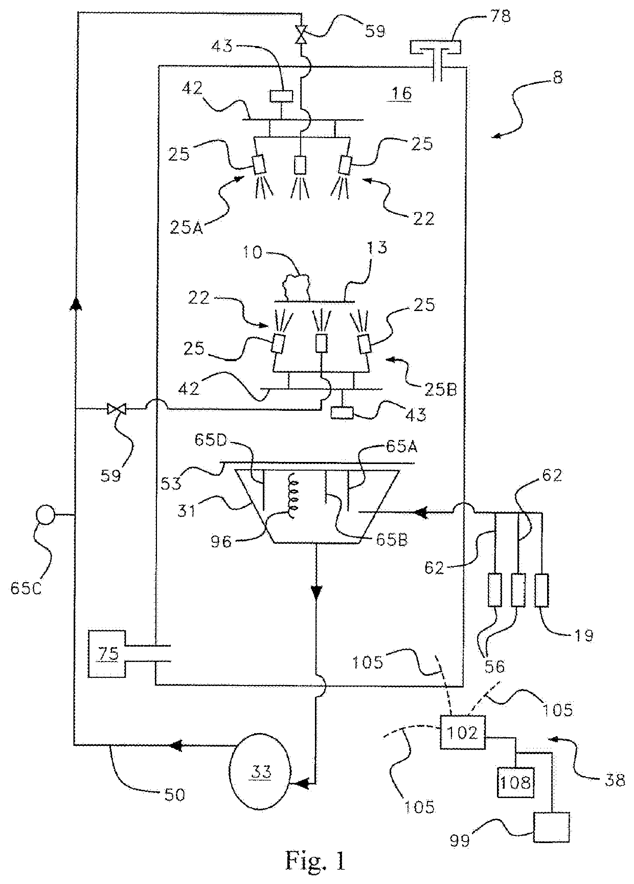
[0090]The apparatus 100 in FIG. 7 is similar to the embodiment 8 in FIG. 1 and like numerals refer to like components. In the embodiment in FIG. 7, a flexible hose member 104 connects to the lower spray header 110. The lower spray header 110 has a fitting 112 to which the flexible hose member 104 can attach. The fitting 112 can be in addition to the fittings to which the lower nozzles 25B are attached. Alternatively, one of the lower spray nozzles 25B can be removed and the flexible hose member 104 can be connected to the lower spray header 110 in the fitting from which the one lower spray nozzle 25B was removed. The flexible hose member 104 includes a valve 118 operable to shut off flow through the flexible hose member 104. At the end of the flexible hose member 104 is a nozzle 124.

[0091]Located on and connected to the platform 13 is an adjustable holding member 128.

[0092]FIG. 8 shows a view of the interior of the chamber 16. Located on the platform 13 is the part 10. The flexible ...

embodiment 100

[0096]In the embodiment 100 disclosed in FIG. 7, the flexible hose member 104 and holding member 128 are provided as removable parts that can be installed in the apparatus 100 by an operator when needed. In an alternative embodiment, the flexible hose member 104 and holding member 128 may be provided as non-removable parts that are permanently installed in the apparatus 100.

[0097]In further alternative embodiments, the flexible hose can be adapted for use in a support material removal system like the one disclosed in U.S. Published patent application 20170348910, filed Jun. 1, 2017, the entire disclosure of which is incorporated by reference herein.

[0098]FIG. 11-13 show yet another embodiment of an apparatus 400 for surface finishing of and support removal from additively manufactured parts. Like the embodiment 100 in FIGS. 7-9, the apparatus 400 in FIGS. 11-13 is useful for removal of support material from additively manufactured parts that have internal chambers, cavities, or pass...

embodiment 400

[0106]In the embodiment 400 disclosed in FIG. 11, the submersion tank 150, the input hose 162, and the drainage hose 178 are provided as removable parts that can be installed in the apparatus 400 by an operator when needed. In an alternative embodiment, the submersion tank 150, the input hose 162, and the drainage hose 178 may be provided as non-removable parts that are permanently installed in the apparatus 400.


PUM

PropertyMeasurementUnit
Sizeaaaaaaaaaa
Flexibilityaaaaaaaaaa
Proximity effectaaaaaaaaaa

Abstract

An apparatus and method for removing support material from and/or smoothing surfaces of an additively manufactured part (the “AM part”) is disclosed. The apparatus may include a chamber, a support surface within the chamber, and one or more nozzles within the chamber. The nozzles may be the same size or different sizes. The support surface may be configured to support the AM part. The support surface may have one or more openings sized and configured to allow the fluid to pass through the opening(s). The nozzles may be configured to spray a fluid at the AM part, and the spray may be an atomized or semi-atomized spray of the fluid. For removing support material from parts with internal spaces, such as cavities or passages, the apparatus can include a nozzle at the end of an adjustable flexible hose member that can be adjusted to spray into an internal space of the part. Alternatively, for removing unwanted support material from multiple parts with internal spaces, the apparatus may include a submersion tank.

Description


Claims


Application Information

Patent Timeline
Owner POSTPROCESS TECH INC
Why Eureka
Try Eureka