
Armature of relay

a technology of armature and relay, which is applied in the direction of electrical apparatus, electrical relay details, contacts heating/cooling, etc., can solve the problems of overflow, burning, and limited space for the armature installed in the relay, and achieve the effect of high current and flexible and stabl

Inactive Publication Date: 2021-01-14
SONG CHUAN PRECISION
View PDF0 Cites 3 Cited by
  • Summary
  • Abstract
  • Description
  • Claims
  • Application Information

AI Technical Summary

Benefits of technology

This patent is about a new design for a relay that makes the armature in the relay more flexible and stable within the room of the relay case. This allows the armature to work under high current. The new design also includes an elongate hole that improves heat dissipation. The technical effects of this design are improved stability and better heat dissipation, which ensures the reliable functioning of the relay.

Problems solved by technology

The room in relays is limited so that the armature installed in the relay has a limited space to pivot.
Another problem is that if a larger current is needed to be controlled, a shorter armature may cause overflow and burning.

Method used


Image

  • Armature of relay
  • Armature of relay
  • Armature of relay

Examples


Embodiment Construction

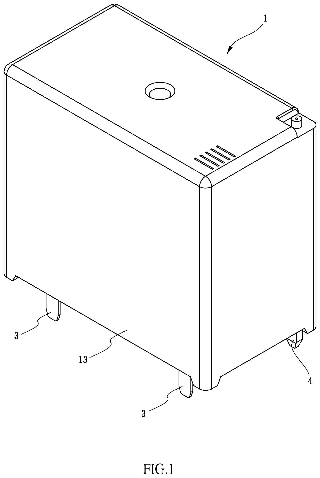
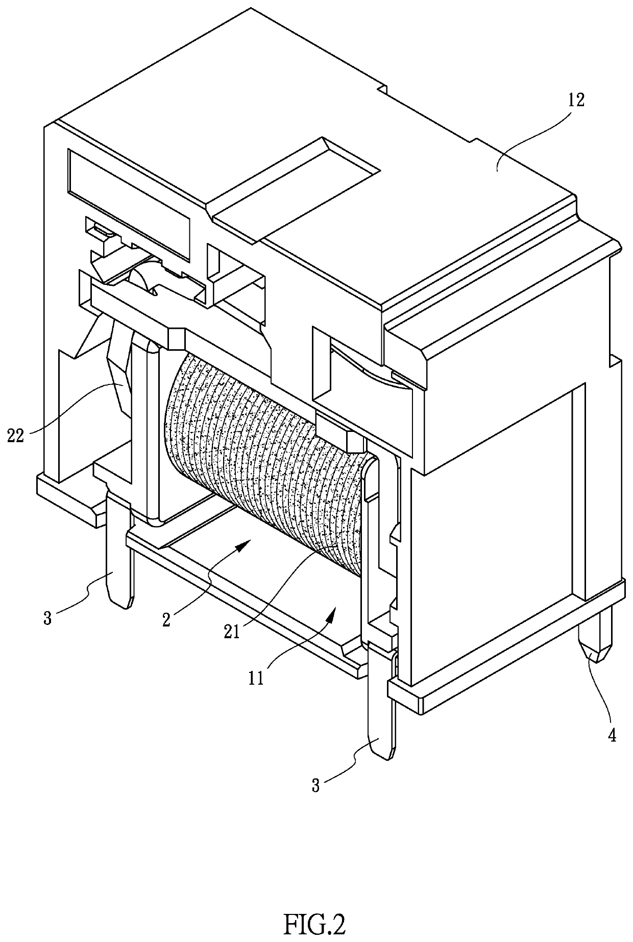
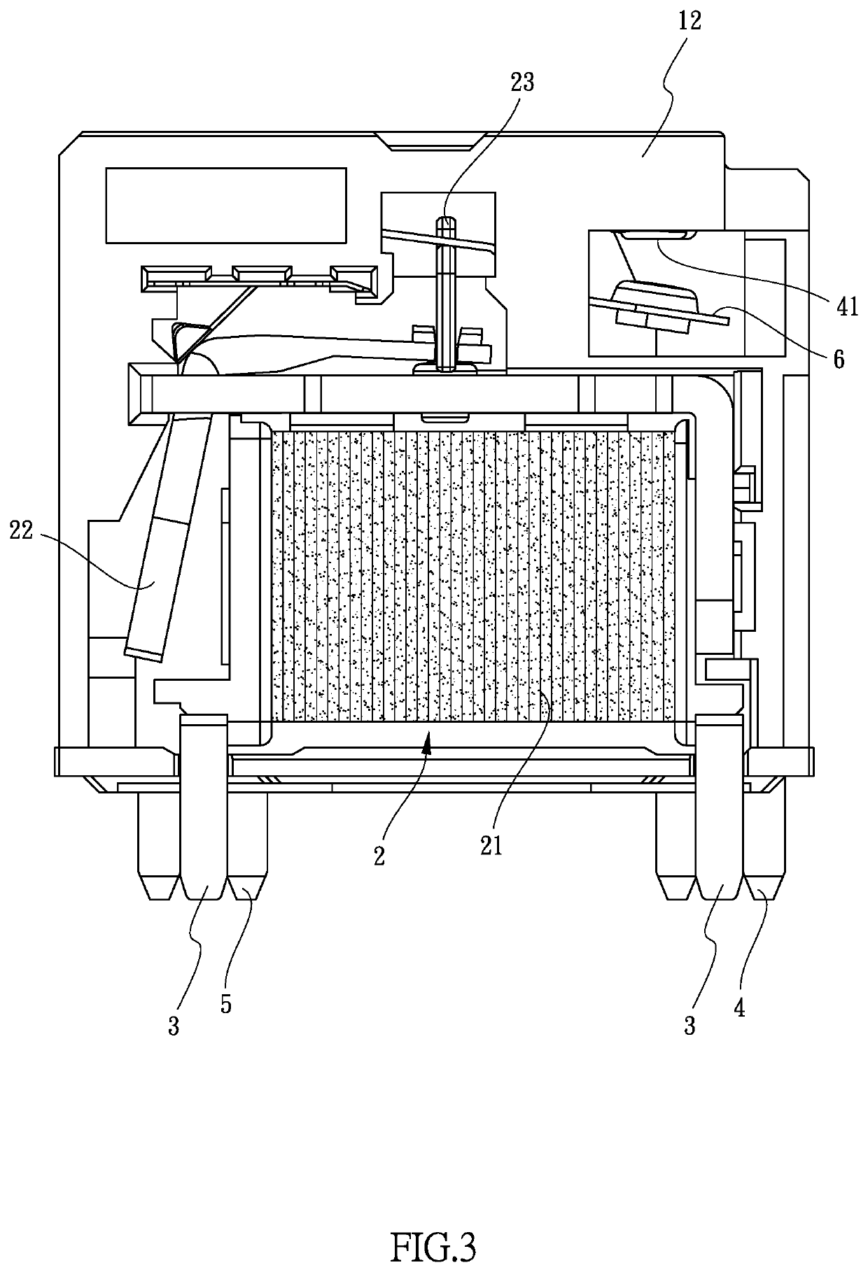
[0019]Referring to FIGS. 1 to 5, 5A and 6, the relay of the present invention comprises a case 1 which is a rectangular case and has a room 11 defined therein. Specifically, the case 1 includes a body 12 and a housing 13 which is mounted to the body 12. The room 11 is formed in the body 12. A coil unit 2 is located in the room 11. Multiple first legs 3 each have the first end thereof connected to the coil unit 2, and the second end of each first leg 3 extending beyond the case 1. The second ends of all of the first legs 3 are located on the first side of the case 1. A second leg 4 has the first end thereof located in the room 11 and forms a contact 41, and the second end of the second leg 4 extends beyond the case 1 and located one the second side of the case 1. A third leg 5 includes an upright section 51 and a transverse section 52, wherein the transverse section 52 extends from one side of the first end of the upright section 51 and is located in the case 1 The upright section 51...


PUM


Abstract

A relay includes a case and a coil unit is located in the case. Multiple first legs each have the first end thereof connected to the coil unit, and the second end thereof extending beyond the case. A second leg has the first end thereof located in the case and forms a contact, and the second end of the second leg extends beyond the case. A third leg includes an upright section and a transverse section which extends from the upright section and located in the case. The upright section has one end thereof extending beyond the case. An armature has a connection section connected to the transverse section, and a main section located beneath the contact. The main section includes an elongate hole defined axially therethrough to have better heat dissipation. The connection section increases conductive area and flexibility of the armature in the case.

Description

BACKGROUND OF THE INVENTION1. Fields of the invention[0001]This patent application is a Continuation-in-Part patent application of applicant's former patent application with the application Ser. No. 16 / 166,341, filed on Oct. 22, 2018.2. Descriptions of Related Art[0002]The conventional relay includes an input circuit and an output circuit so as to use small current to control large current R) protect the electric devices. The room in relays is limited so that the armature installed in the relay has a limited space to pivot. Conventionally, one end of the armature is welded to the leg of the relay so that the range that the armature is limited. Another problem is that if a larger current is needed to be controlled, a shorter armature may cause overflow and burning.[0003]The present invention is intended to provide an armature of a relay, and the purpose is to increase the main section of the armature to successfully use small current to control large current.SUMMARY OF THE INVENTION[...

Claims


Application Information

Patent Timeline
Patent Type & Authority Applications(United States)
IPC IPC(8): H01H50/18H01H50/36
CPCH01H50/18H01H50/36H01H1/62H01H50/12H01H50/14H01H50/26H01H50/56H01H50/58H01H50/641
Inventor WU, SUNG-JEN
Owner SONG CHUAN PRECISION
Learn More