Dither pattern forming method, image processing apparatus, and image processing method
a pattern forming and pattern technology, applied in the field of dither pattern forming method, image processing apparatus, image processing method, can solve the problems of loss of blue noise properties, and insufficient dispersibility of the arrangement of dots actually printed on the printing medium, and achieve excellent dot dispersibility and reduce graininess
- Summary
- Abstract
- Description
- Claims
- Application Information
AI Technical Summary
Benefits of technology
Problems solved by technology
Method used
Image

Examples
first embodiment
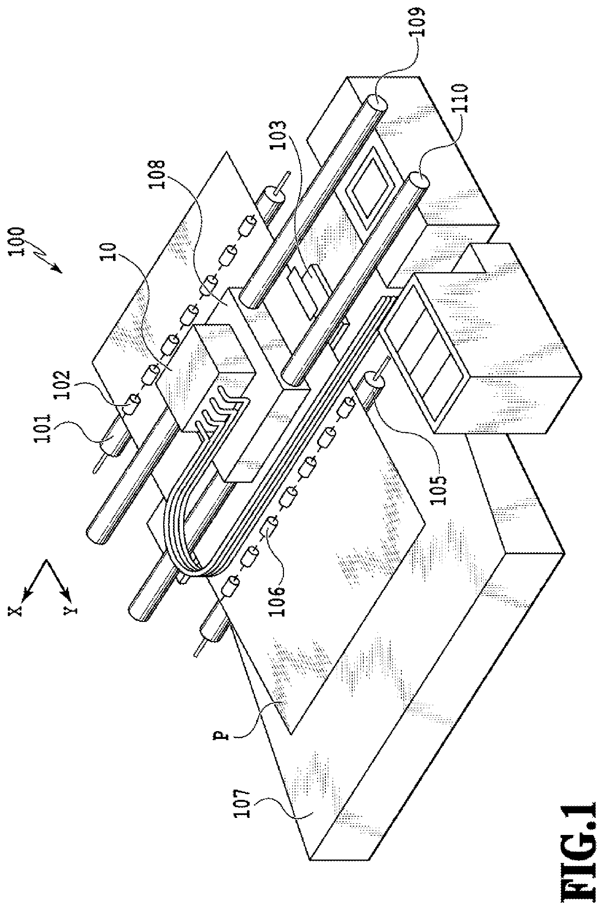
[0030]FIG. 1 is a perspective diagram illustrating an overview of a printing part of a serial-type ink jet printing apparatus 100 used in this embodiment. A nip portion between a conveyance roller 101 arranged on a conveyance route and pinch rollers 102 associated with the conveyance roller 101 conveys a printing medium P fed to the printing part in a Y direction (sub-scanning direction) along an arrow in FIG. 1 with the rotation of the conveyance roller 101.
[0031]A platen 103 is provided at a printing position facing a surface of an ink jet form-printing head 10 in which ejection ports are formed (ejection port surface) and supports a back surface of the printing medium P from below to maintain a constant distance between a front surface of the printing medium P and the ejection port surface of the printing head 10. An area of the printing medium P done with the printing above the platen 103 is nipped by a discharge roller 105 and spurs 106 associated with the discharge roller 105 ...
second embodiment
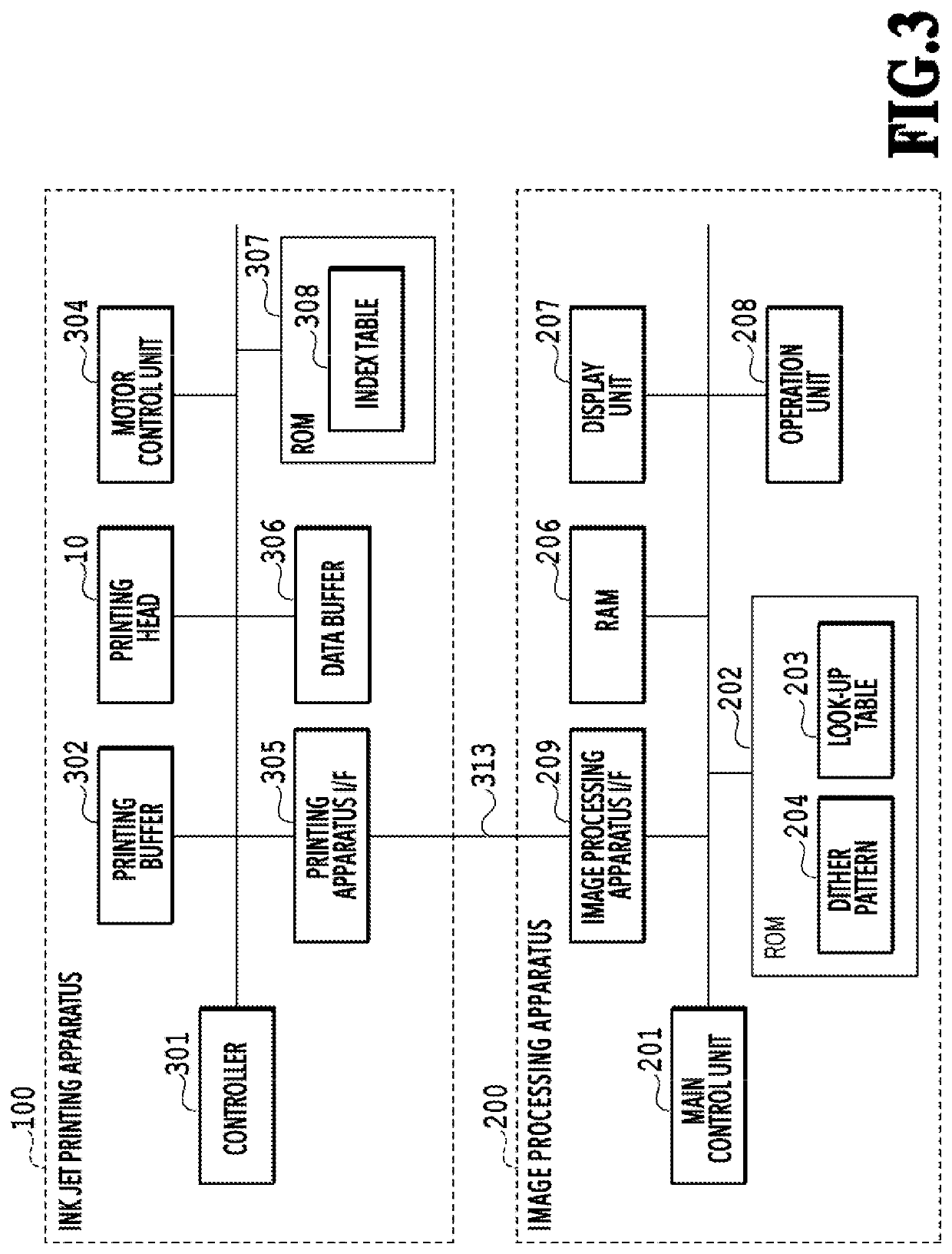
[0083]The printing apparatus and the image processing apparatus described in FIGS. 1 to 3 are used to perform the image processing according to the flowchart of FIG. 4 also in this embodiment. It should be noted that, in this embodiment, the gradation values of 0 to 255 are quantized (gradation reduction) not to two values of 0 and 1 but to three or more values.
[0084]FIG. 12 is a flowchart describing the quantization processing executed in S404 of FIG. 4 by the main control unit 201 of the image processing apparatus 200 in this embodiment. This processing is performed by the main control unit 201 sequentially on each pixel of 600 dpi of the CMYK data in which each color is 8 bits.
[0085]Once this processing is started, first, in S201, the main control unit 201 obtains an input value In as the pixel value of the processing target pixel and obtains a threshold Dth corresponding to the pixel position of the processing target pixel from the dither pattern 204.
[0086]In S202, the main cont...
third embodiment
[0111]Also in this embodiment, the printing apparatus and the image processing apparatus described in FIGS. 1 to 3 are used to perform the image processing according to the flowchart of FIG. 4. Also in this embodiment, as with the second embodiment, the gradation values of 0 to 255 are quantized to three values. However, it should be noted that, in this embodiment, a small dot is printed in the pixel in which the quantization value is 1, and a large dot is printed in the pixel in which the quantization value is 2.
[0112]FIG. 17 is a diagram illustrating dot arrangement patterns used for the index development processing (S405 of FIG. 4) of this embodiment. As with the above-described embodiment, within the 2×2-pixel area, a pixel in which the small dot is printed and a pixel in which the large dot is printed are determined associating with the corresponding quantization values. In the dot arrangement patterns A to D, the pixel in which the small dot is printed if the quantization valu...
PUM
 Abstract
Description
Claims
Application Information
 - R&D Engineer
- R&D Manager
- IP Professional
- Industry Leading Data Capabilities
- Powerful AI technology
- Patent DNA Extraction
Browse by: Latest US Patents, China's latest patents, Technical Efficacy Thesaurus, Application Domain, Technology Topic.
© 2024 PatSnap. All rights reserved.Legal|Privacy policy|Modern Slavery Act Transparency Statement|Sitemap